
90 Degree Bevel Gears – Right-Angle Drive, All Materials
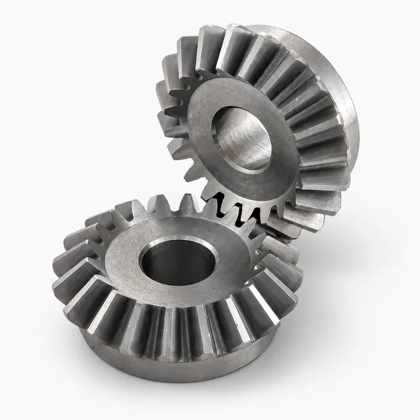
Korea Ever-Power 90 degree bevel gears — also called right-angle bevel gears — transmit power between two shafts positioned at exactly 90° to each other. The 90° configuration is the universal standard for bevel gear drives in industrial machinery, automotive differentials, machine tools, robotics, aerospace landing gear, marine propulsion, and agricultural equipment. Available in straight, spiral, and zero-degree spiral tooth forms across the full material range: steel alloys, cast iron, stainless, brass, aluminium, copper, zinc, POM, and PEEK. Modules M3 to M20. Full seven-step manufacturing process with rigorous quality control at every stage.
Product Overview
90 degree bevel gears, also called right-angle bevel gears, are bevel gears where the two intersecting shaft axes meet at precisely 90 degrees. This is the most common bevel gear configuration by a significant margin — the 90° right-angle configuration appears in virtually every sector of mechanical engineering because the need to transmit power between perpendicular shafts is fundamental to machine design. Motor outputs run along one axis; the driven shaft must frequently run at 90° to it to fit the machine geometry. The 90° bevel gear pair solves this direction-change requirement in a compact envelope with high efficiency.
Korea Ever-Power produces 90 degree bevel gears across the full range of tooth forms — straight bevel for low-speed simple drives, spiral bevel for high-speed quiet drives, and zero-degree (Zerol) spiral bevel where zero net axial thrust is required while keeping the same bearing arrangement as a straight bevel pair. The full material range is available: steel alloys, cast iron, stainless steel, brass, copper, aluminium, zinc, POM, and PEEK. Module range covers M3 through M20 for industrial applications and M0.15 through M2.2 for precision miniature drives. All seven stages of the manufacturing process — from gear design through quality control — are carried out in-house.
The performance of a 90 degree bevel gear set depends on selecting the correct tooth form and material for the application's speed, torque, and noise requirements. A right-angle bevel gear pair for a slow heavy conveyor has entirely different tooth form, material, and accuracy grade requirements from one in a high-speed precision instrument. This page covers the engineering considerations that determine those choices.
The 90° Geometry — Pitch Cone Angles and Gear Ratio
In a 90 degree bevel gear pair, the pitch cone angle of each gear is determined by the gear ratio. Because the two shaft axes intersect at 90°, the sum of the two pitch cone angles must equal 90°. For a 1:1 miter gear pair (equal tooth counts), both gears have a 45° pitch cone angle. For unequal ratios, the pitch cone angles are calculated from:
Pitch cone angle of the pinion = arctan(1 / gear ratio)
Pitch cone angle of the wheel = 90° − pinion pitch cone angle
Example: for a 3:1 ratio 90° bevel set, the pinion pitch cone angle is arctan(1/3) ≈ 18.4° and the wheel pitch cone angle is 90° − 18.4° = 71.6°.
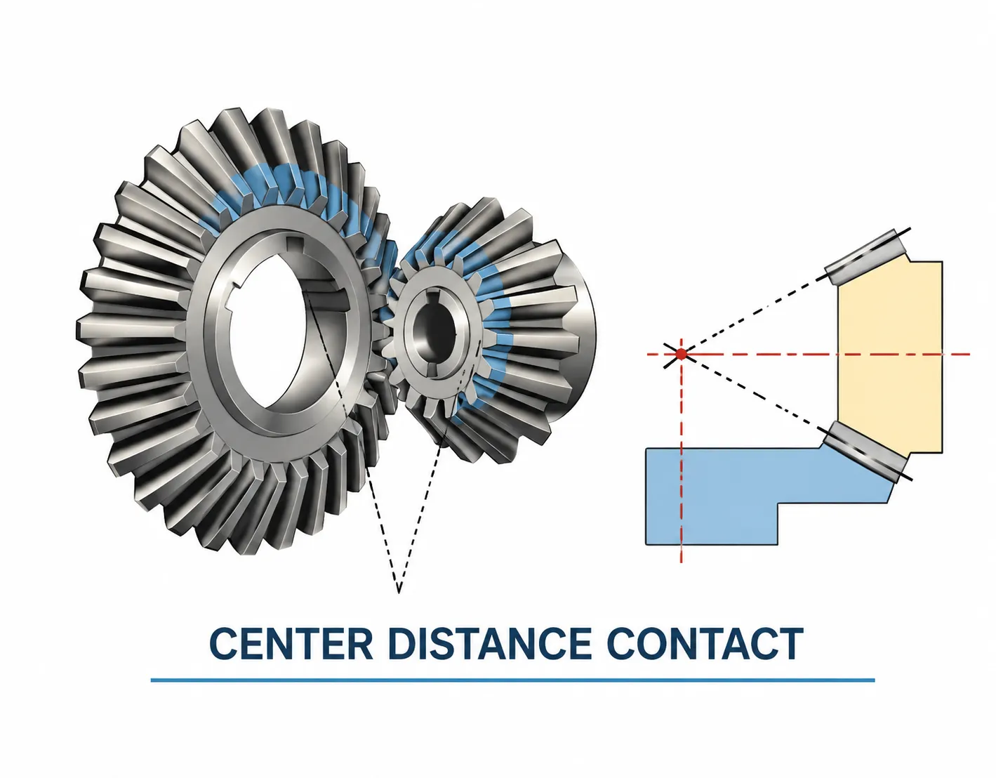
This geometric relationship has a practical implication: for a given 90° bevel gear pair, the pitch cone angles are fixed by the ratio. They cannot be independently adjusted. If the housing centres the gear pair incorrectly — placing one gear closer to or further from the pitch apex than its nominal position — the contact zone shifts to the tooth edge, concentrating stress. This sensitivity to mounting distance is the primary installation requirement for any 90 degree bevel gear pair, and is why correct shim selection during assembly is essential.
Miter gears — the special 1:1 case
When both gears in a 90° set have equal tooth counts (and equal pitch cone angles of 45°), they are called miter gears. Both gears are identical, produced from the same die and tooling — an advantage for spare part stocking and production economies. A single miter gear part number covers both members of the 1:1 pair.
Tooth Form Selection for 90 Degree Bevel Gear Drives
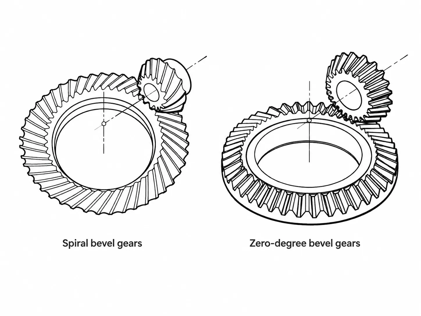
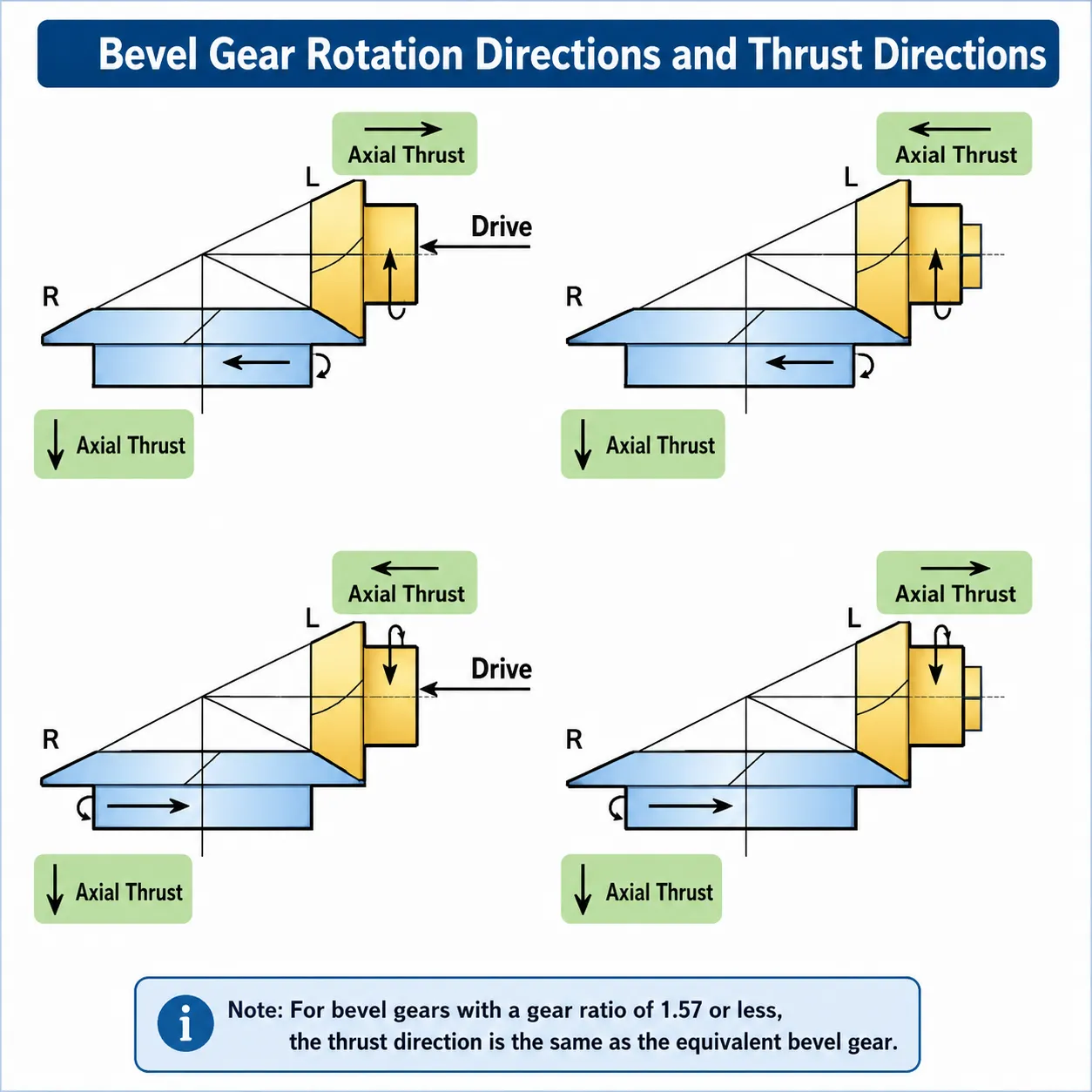
All three bevel gear tooth forms are available for 90° configurations from Korea Ever-Power. The correct form depends on the application's pitch-line speed, noise requirements, and whether axial thrust management is a design constraint.
Straight Bevel — Low Speed, Simple Drives
All teeth along the face width engage simultaneously at each mesh cycle. No axial thrust generated. Manufacturing is simpler and less expensive than spiral forms. Suitable for 90° drives operating below approximately 3 m/s pitch-line speed where noise from the impact engagement does not exceed the application's limit, and where simplicity of bearing arrangement (no axial thrust reaction needed) is valued. Standard in slow industrial drives, agricultural equipment, and general-purpose gearboxes at moderate speed.
Spiral Bevel — High Speed, Quiet Operation
Curved teeth engage progressively across the face width, sharing load between multiple tooth pairs simultaneously. Significantly lower noise and vibration at moderate and high pitch-line speeds than straight bevel gears. Generates axial thrust (direction depends on spiral hand and rotation direction) — bearings must carry this thrust load. Standard for 90° drives above 3 m/s pitch-line speed, in automotive differentials, high-speed industrial gearboxes, printing press cross-drives, and any application where noise or vibration is a product quality criterion.
Zero-Degree (Zerol) — Zero Thrust, Curved Tooth
Curved circular-arc tooth with zero mean spiral angle. Produces the same zero axial thrust as a straight bevel gear while gaining the localised contact tolerance benefit of the spiral form. Directly interchangeable in the same housing and bearing arrangement as a straight bevel pair. Used in 90° drives where noise improvement over straight bevel is desired but the bearing design cannot accommodate the axial thrust of a standard spiral bevel gear — reversing drives, instrument drives, and direct drop-in replacement upgrades for worn straight bevel pairs.
Seven-Step Manufacturing Process
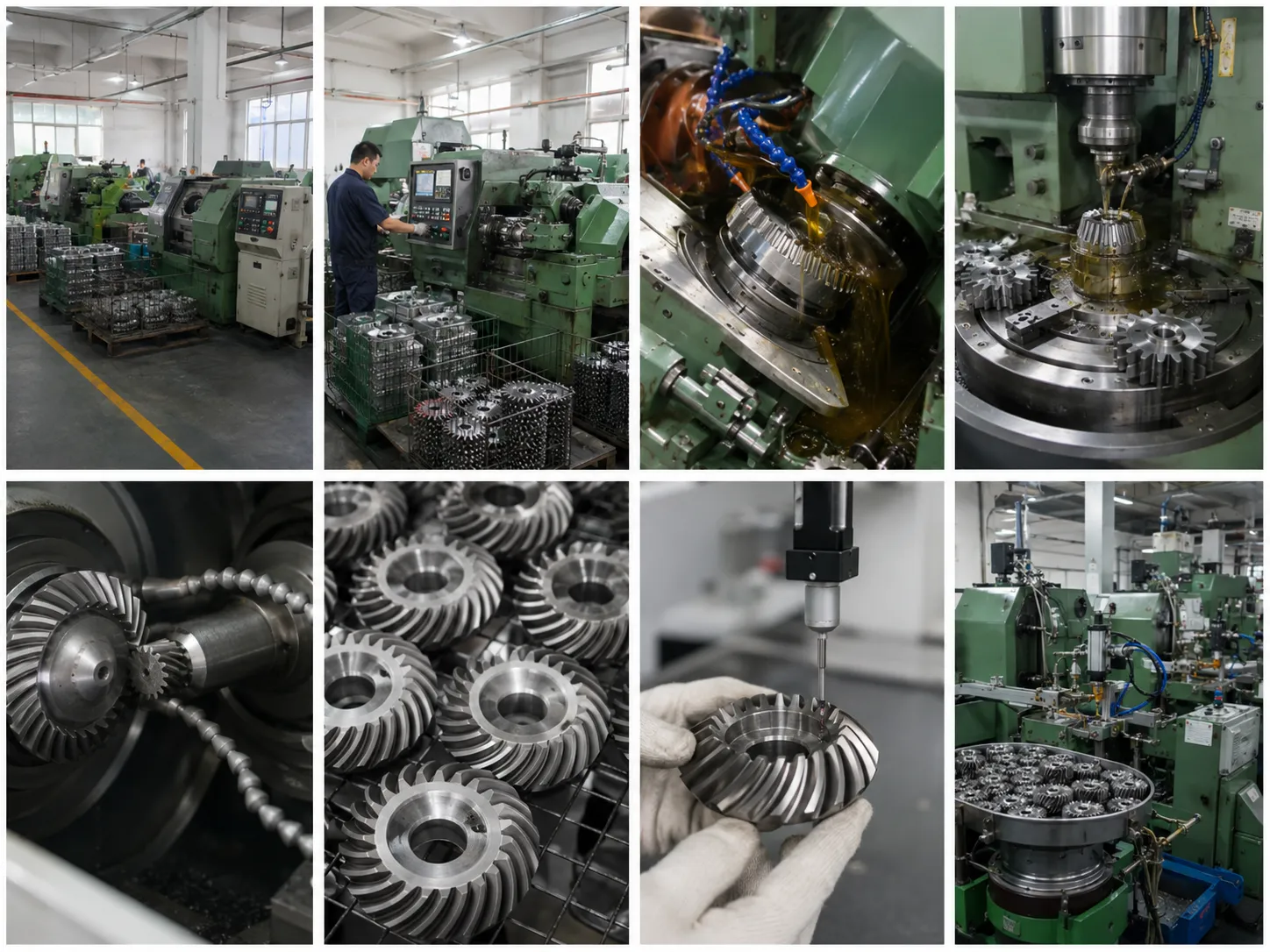
Korea Ever-Power's manufacturing process for 90 degree bevel gears follows a seven-stage sequence. Each stage contributes to the finished gear's dimensional accuracy, surface quality, mechanical properties, and traceability.
- Gear design — gear geometry is established from the customer's specification: shaft intersection angle (90° standard), module, tooth count, pressure angle, and spiral angle (for spiral forms). CAD software generates the complete geometric definition before any material is ordered.
- Material selection — material is selected from steel alloys, cast iron, stainless, brass, copper, aluminium, zinc, POM, or PEEK based on load capacity, environmental requirements, and regulatory constraints. Raw material is verified for grade and chemistry at goods receipt.
- Gear cutting — teeth are cut on specialised CNC bevel gear machines. The method — Gleason face milling, Klingelnberg face hobbing, or straight bevel generating — is selected based on the tooth form and accuracy grade required.
- Heat treatment — carburising and quenching, through-hardening, nitriding, or material-specific treatment is applied to achieve the required surface hardness and core toughness. The time-temperature curve is recorded per batch.
- Machining and finishing — post-hardening grinding, lapping, or honing corrects distortion from heat treatment and achieves the final accuracy grade and surface roughness.
- Gear assembly verification — matched pairs are run on a roll-test bench with the contact zone verified against the reference pattern before packing. Shim recommendations for installation are included with the shipment.
- Quality control — dimensional inspection (CMM), hardness testing, surface roughness measurement, and review of all process documentation are completed before the gear is released for shipment.
Technical Specifications
| Parameter | Specification |
|---|---|
| Configuration | 90 degree (right-angle) bevel gear — shaft axes intersect at 90° |
| Tooth Form | Straight bevel, spiral bevel, or zero-degree (Zerol) spiral bevel |
| Module Range (Industrial) | M3 – M20; outer diameter up to 1200 mm |
| Module Range (Precision) | M0.15 – M2.2; outer diameter Φ3 mm – Φ120 mm |
| Gear Ratios Available | 1:1 (miter) through any ratio; standard and custom ratios per drawing |
| Material Options | Steel alloys, cast iron, stainless steel (304/316), brass, copper, aluminium, zinc alloy, POM, PEEK — full range |
| Accuracy Grade | DIN 5 – DIN 9 / AGMA 7 – AGMA 13 / JGMA 1 – JIS 6 / ISO 6; grade per application |
| Manufacturing Standard | ISO, DIN, ANSI, JIS, BS, and non-standard; Gleason and Klingelnberg methods |
| Heat Treatment | Carburising & quenching, through-hardening, nitriding, material-specific routes |
| Adjustable Gear Ratio | Speed and torque ratio adjusted by specifying tooth count on each gear |
| Positional Accuracy | Suitable for high-accuracy motion control at AGMA 12–13 grades |
| Surface Treatment | Full range: zinc-plated, nickel-plated, passivation, anodisation, Dacromet, black oxide, phosphating, powder coating |
| QA Documentation | Chemical composition, mechanical performance, UT (optional), heat treatment curve, dimensional inspection, roll-test contact photograph |
| OEM / ODM | Full service; CAD drawings produced for customer approval; reverse engineering from sample |
Five Common Operating Problems and Solutions
90 degree bevel gear pairs are reliable in service when correctly specified, installed to the correct mounting distance, and properly lubricated. The following covers the five most frequently reported field problems and the engineering response to each.
Excessive Noise or Vibration
Cause: misalignment (mounting distance error shifting contact to tooth edge), worn tooth flanks, or insufficient lubrication creating metal-to-metal contact. Solution: perform blue-dye contact check; if contact is at heel or toe, adjust shims under the bearing cup to correct mounting distance. Replace worn gears. Confirm oil viscosity grade and level per the gearbox specification. If noise appears at a specific speed, investigate gear mesh frequency resonance in the shaft or housing structure.
Tooth Wear or Damage
Cause: operating load exceeding the gear's rated torque, inadequate lubrication film, or abrasive contamination in the oil. Solution: verify actual operating torque against the gear's rated capacity. Change oil and inspect for metallic debris or water contamination. Fit a magnetic drain plug to monitor wear debris. If overload is confirmed, upsize the module or upgrade the material grade. If wear is at the tooth edge, correct the mounting distance first before attributing the cause to load.
Insufficient Lubrication
Cause: oil level below the large-end tooth depth, wrong viscosity grade, degraded oil past its service life, or splash lubrication not reaching the mesh in certain mounting orientations. Solution: confirm oil level against the dipstick mark. Verify the oil grade against the gearbox data plate — ISO VG 220 EP for most enclosed industrial right-angle bevel drives. Change oil at the specified interval and drain the initial fill at 500 hours to remove running-in debris. For non-standard mounting orientations, a forced lubrication circuit may be needed.
Misalignment
Cause: housing bore machining error, incorrect shim stack under bearing cups, or angular shaft misalignment exceeding the gear's contact tolerance. Solution: perform a full contact pattern check before first load. Axial misalignment (mounting distance error) is corrected by adjusting shims under the bearing cup. Angular misalignment requires housing bore correction — shimming cannot compensate for a bore that is machined out of square with the shaft axis. Use dial indicators or laser alignment tools during installation of large right-angle bevel gear sets.
Overload or Excessive Torque
Cause: peak torque events — sudden starts, hard stops, jam events, or process overloads — exceeding the gear's design limit. Evidence is tooth chipping or root fracture rather than the gradual surface pitting associated with sustained overload. Solution: inspect the oil sump debris — chip fragments confirm the failure mode. Upgrade to a case-hardened material grade with tougher core for impact resistance (20CrNi2MoA over 20CrMnTi). Fit a torque limiter upstream of the gear set, or reduce the drive motor ramp rate to limit the starting torque spike.
Applications
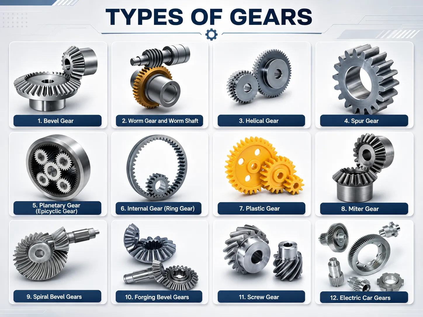
The 90 degree bevel gear's universality means it appears in virtually every sector of mechanical engineering. The following covers the ten principal application categories confirmed in the product specification — from machine tools to marine propulsion to medical equipment.
⚙ Machinery & Equipment
Machine tools, printing presses, packaging machinery, and conveyors — the largest single application category for 90 degree bevel gears. Right-angle direction changes between motor output shaft and driven machine shaft appear in virtually every production machine.
🚗 Automotive
Differentials, power take-off units, and steering systems. The automotive differential's ring-and-pinion set is a 90 degree hypoid bevel gear configuration; the internal differential bevel gear set is a straight or spiral 90° configuration.
🤖 Robotics
Robotic arm joints and manipulators using 90 degree bevel gears to transmit torque at right angles between motor and output axis. Precision grades AGMA 12–13 in stainless or aluminium for cleanroom-compatible robot configurations.
✈ Aerospace
Aircraft landing gear actuation systems, engine accessory gearboxes, and rotorcraft transmissions using 90 degree spiral bevel gears at the highest accuracy grades with full material traceability documentation.
⚙ Power Transmission
Gearboxes, speed reducers, and drivetrains where the primary function of the bevel gear stage is redirecting the power flow through 90° at the specified ratio. The most common industrial gearbox configuration is a spiral bevel right-angle input stage combined with one or more parallel helical stages.
🏺 Industrial Mixers
Heavy-duty industrial mixers and agitators for chemical processing, food production, and pharmaceutical manufacturing. Right-angle bevel gear stages transmit the motor torque from the horizontal drive shaft to the vertical agitator shaft.
🛠 Machine Tools
Milling machines, lathes, and drilling machines using 90 degree bevel gears in angle head attachments, dividing heads, and feed axis bevel stages. AGMA 12–13 precision required for the accuracy grade to translate to the machined workpiece.
⚓ Marine
Marine propulsion angle drives, steering mechanisms, deck winches, and bow thruster gearboxes. Stainless steel or corrosion-protected alloy steel with classification society documentation (DNV, ABS, BV) for new-build vessel applications.
🌿 Agricultural Equipment
Tractors, harvesters, and PTO-driven implements using 90 degree bevel gears in PTO angle drives, header gearboxes, and main transmission bevel stages. Alloy steel carburised and quenched is the standard specification for agricultural right-angle drives.
💊 Medical Equipment
Imaging devices, robotic surgery systems, and precision instruments using 90 degree bevel gears at AGMA 12–13 in stainless, PEEK, or brass for motion control accuracy, biocompatibility, and sterilisation compatibility.
Frequently Asked Questions
What makes 90 degree bevel gears more compact than worm gear reducers at the same ratio?
Bevel gears transmit power at 90° with efficiency typically above 97% per stage; worm gear reducers at the same ratio operate at 50 to 90% efficiency depending on the lead angle. The energy that a worm gear loses as heat must be dissipated through the gearbox housing — requiring a larger, heavier housing with adequate heat dissipation surface area. A right-angle bevel gear gearbox, by contrast, loses very little power as heat and can be more compact at equivalent output torque. For continuous-duty drives above approximately 5 kW where a 90° direction change is needed, the life-cycle energy saving from a bevel gear stage over a worm stage is substantial and typically justifies the higher gear cost.
How do I adjust the gear ratio of a 90 degree bevel gear set without changing the housing?
The gear ratio is adjusted by changing the tooth counts on the pinion and wheel. Increasing the wheel tooth count (or decreasing the pinion count) increases the ratio; the inverse decreases it. When changing the ratio in an existing housing, the pitch cone angles change — which means the distance from each gear's pitch apex to its mounting datum face changes. The housing must accommodate these changed apex positions, which typically means the bearing cup positions must move or the shaft lengths must be adjusted. For a small ratio change within the same module, it may be possible to remain within the original bearing cup positions by adjusting shims; for a large ratio change, a new housing design is usually required. Submit the existing housing drawing and the new required ratio to our engineering team and we will advise on feasibility.
What is the difference between a 90 degree bevel gear and a miter gear?
A miter gear is a specific subset of the 90 degree bevel gear family — it is a 90° bevel gear pair with a 1:1 ratio, meaning both gears have the same tooth count and identical 45° pitch cone angles. Because both gears are identical, a miter gear set is produced from a single part number and the same tooling. Any 90° bevel gear pair with an unequal tooth count — where the ratio is other than 1:1 — is a standard right-angle bevel gear rather than a miter gear. The term "miter gear" is sometimes used loosely to mean any 90° bevel gear, but the correct technical definition is the equal-tooth-count 1:1 ratio pair.
Why is the blue-dye contact check important during 90 degree bevel gear installation?
The contact check with engineer's blue (applied to the tooth surface, pair rotated by hand) shows the position and shape of the actual contact zone on the tooth face before any load is applied. For a correctly installed 90 degree bevel gear pair, the contact zone should sit between the toe and the centre of the tooth face at mid-tooth height, not touching any edge. Under full operating load, elastic deflections shift the contact toward the heel and pitch line; the no-load contact zone is offset toward the toe to compensate for this shift. If the no-load contact is already at mid-face or heel, it will move to the heel edge under load, concentrating stress and initiating pitting within the first hours of loaded operation. The contact check allows correction by shim adjustment before any damage occurs — it is the single most important installation step for any 90 degree bevel gear pair.
Can Korea Ever-Power produce a 90 degree bevel gear to replace a worn gear for which no drawing exists?
Yes. Korea Ever-Power specialises in reverse engineering from worn or undocumented samples. Send us the worn gear (or both gears of the pair if possible) along with measurements of the outer diameter, tooth count, bore diameter, face width, hub diameter, and hub length of each gear. Our engineering team measures the module, spiral angle (for spiral forms), and pitch cone angle from the physical sample, produces a complete production drawing for your approval, and manufactures to that drawing. For gears where the module is difficult to measure from a worn sample (teeth may be worn below standard profile), we measure the outer diameter and tooth count and calculate the module from these. The customer receives and approves the production drawing before any cutting begins. Contact our team with your worn gear and we will confirm the reverse engineering process and lead time.
Customer Reviews
"We replaced a worn 90 degree spiral bevel gear pair in a conveyor head drive without a drawing — sent the worn gears to Ever-Power and received a production drawing for approval within four days. The replacement pair arrived with the roll-test contact photo showing mid-face contact. Installed with the shim recommendation they included; blue-dye check on installation matched the reference print. The drive has run 14 months without further maintenance."
Ryu Hyeon-seok | Plant Engineer, Gyeongnam Logistics Centre · Q1 2026
"We switched our 5 kW continuous agitator drives from worm gear reducers to 90 degree bevel gear stages three years ago. Energy metering shows 14% reduction in drive energy consumption across 24 agitator units. Ever-Power's right-angle spiral bevel stages run at consistent efficiency and we have had no unplanned downtime on any of the 24 units in 36 months."
Jang Hyeon-jun | Process Equipment Manager, Chungnam Chemical Plant · Q3 2025
"We build CNC milling machine angle heads and specify AGMA 12 90 degree spiral bevel gears in 20CrMnTi carburised. Ever-Power's gears arrive with a dimensional report showing tooth spacing error within the AGMA 12 tolerance on every piece. Positional accuracy of the angle head has met the 0.005° specification on all heads built in the past two years."
Kim Tae-yang | Engineering Manager, Daegu Machine Tool Accessories · Q4 2025
"We needed M16 90 degree bevel gears in alloy steel with DNV material certification for a bulk carrier deck winch gearbox. Ever-Power arranged the DNV surveyor attendance for material testing and dimensional inspection. Certificates issued and accepted by the classification society for the vessel record. The gearbox has completed one annual survey cycle without any gear-related issues."
Oh Seong-jun | Marine Technical Superintendent, Busan Shipping Services · Q2 2025
"We manufacture robotic arm wrist joints for a collaborative robot programme. The M0.8 AGMA 13 90 degree spiral bevel gears in 316L stainless from Ever-Power have held their backlash specification through 2 million wrist cycles in our endurance testing — zero measurable change in tooth spacing error over the test duration. Cleanroom packaging was arranged on request for our assembly environment."
Shin Ha-eun | Robotics Mechanical Engineer, Suwon Automation Systems · Q1 2026
Request a Quotation for 90 Degree Bevel Gears
Send us your drawing, worn gear sample, or application data — module, tooth count, tooth form (straight / spiral / Zerol), material, accuracy grade, and documentation requirements. For reverse engineering from a worn gear, include outer diameter, tooth count, bore, face width, and hub dimensions. Our engineering team returns a feasibility confirmation and price within two working days.
추가 정보
| Editor |
|---|
연관 상품
-
Plastic Bevel Gears – POM PA PEEK, -40°C to 80°C, 1:1–5:1
-
Metal Bevel Gear – M0.15 to M2.0, 11 Alloys, AGMA 13
-
Medical Bevel Gear – M0.15 to M2.2, ISO 6 / AGMA 13
-
Forging Bevel Gears – Hot & Cold Forged, Custom OEM Supply
-
Differential Gears – Open, LSD, Torque Vectoring, Forged PM
-
Straight Bevel Gear – M3 to M12, DIN6-9, Multi-Material
-
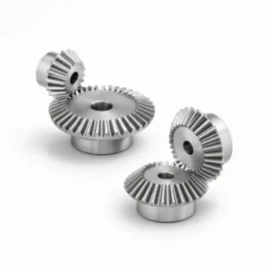
Bevel Gears European Standard – DIN Type A & B, 1:1 to 1:4
-
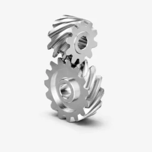
Helical Bevel Gear – Tangential Tooth, Low Noise Bevel Drive
 Korean
  English
  Italian
  French
  Japanese