
Helical Gear Rack | High-Speed Low-Noise Rack and Pinion, Custom OEM
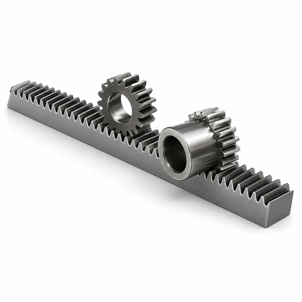
Helical gear racks deliver the higher load capacity, quieter operation, and smoother motion that spur racks cannot match at speeds above 3 m/s — because angled teeth enter mesh progressively, spreading force across multiple contacts at every instant. Ever-Power helical racks are available in modules M1 through M10, standard length 1,000 mm per section with precision-machined half-tooth ends for unlimited butted travel, in C45 carbon steel and 42CrMo alloy steel with carburized tooth flanks at HRC 42-48 and JIS Grade 5 accuracy. Right-hand helix angle 19°31min42sec is standard; left-hand and custom angles are manufactured to drawing. ISO 9001:2015 certified — material certificate, heat treatment record, and pitch error report included with every order.
Helical Gear Rack — Product Overview
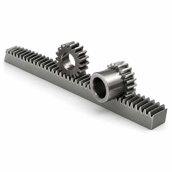
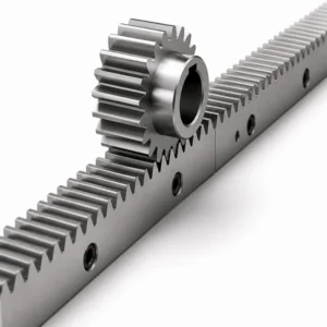
Ever-Power helical gear racks are the preferred choice for any linear drive where noise, load capacity, or speed performance exceeds what a spur rack can deliver. Unlike straight-tooth spur racks — where each tooth engages in a single simultaneous impact — a helical rack has teeth set at an angle across the face so that each tooth enters and leaves mesh progressively. At any given instant, load is shared across multiple teeth rather than concentrated on one, which increases the effective contact ratio, reduces noise and vibration substantially, and allows the same module rack to carry a higher tangential force than its spur equivalent.
Ever-Power standard helical racks are produced in C45 (S45C) medium carbon steel and 42CrMo alloy steel, module M1 through M10, standard length 1,000 mm per section. The tooth area is carburized and heat-treated to HRC 42-48 for surface hardness with a tough core. Side faces are ground flat (side ground included) to provide accurate mounting reference faces. Precision grade is JIS Grade 5 (equivalent to DIN 7 or AGMA Q9), and pitch error per 300 mm is controlled to 0.02 mm at M1 up to 0.052 mm at M10. Half-tooth machined ends allow multiple sections to be butted for unlimited travel with pitch continuity at every joint.
The standard helix angle is 19°31min42sec right-hand, matching the most common helical pinions used in servo-driven CNC gantry systems and pick-and-place automation. Left-hand racks and custom helix angles are available to order. Custom modules, non-standard cross-section dimensions, and special hole patterns are accepted from customer drawings in DXF, DWG, STEP, or PDF format.
Helical Gear Rack — Finish Milled Specification
| Parameter | Value |
|---|---|
| Grado di precisione | JIS Grade 5 (7e25); equivalent DIN 7 / AGMA Q9 |
| Materiale | S45C medium carbon steel (C45); 42CrMo alloy steel available |
| Tipo | Helical rack |
| Treatment of Teeth | Finish milled |
| Hardening | Tooth area carburized, HRC 42-48 |
| Side Ground | Included — side faces ground for accurate mounting reference |
| Pressure Angle | 20° |
| Helix Angle (standard) | 19°31min42sec right-hand; left-hand and custom angles per drawing |
| Standard Length per Section | 1,000 mm; half-tooth machined ends for butted joints |
Helical Gear Rack Dimensional Specifications (Module M1 to M10)
All dimensions in millimetres. L = total length; L2 = pitch per tooth (normal); B = overall width; A0 = face width; A1 = tooth depth reference; D = hole spacing; I = end-to-first-hole; Hole No. = number of mounting holes; A = hole diameter; C1/C2 = counterbore depth/diameter; E = edge distance; D1 = first hole from end; I1 = last hole to end; C3 = thread depth.
| Modulo | L (mm) | L2 (mm) | Tooth No. | B (mm) | A0 (mm) | A1 (mm) | D (mm) | I (mm) | Hole No. | A (mm) | C1 (mm) | C2 (mm) | E (mm) | D1 (mm) | I1 (mm) | C3 (mm) | Pitch Error /300mm (mm) |
|---|---|---|---|---|---|---|---|---|---|---|---|---|---|---|---|---|---|
| 1 | 1000.00 | 3.14 | 300 | 15 | 15 | 14 | — | — | — | — | — | — | — | — | — | — | 0.020 |
| 1.5 | 1000.00 | 6.70 | 200 | 19 | 19 | 17.5 | 62.5 | 125 | 8 | 8 | 7 | 11 | 7 | 31.7 | 936.6 | 5.7 | 0.030 |
| 2 | 1000.00 | 8.50 | 150 | 24 | 24 | 22 | 62.5 | 125 | 8 | 8 | 7 | 11 | 7 | 31.7 | 936.6 | 5.7 | 0.031 |
| 2.5 | 1000.00 | 8.50 | 120 | 24 | 24 | 21.5 | 62.5 | 125 | 8 | 9 | 7 | 11 | 7 | 31.7 | 936.6 | 5.7 | 0.033 |
| 3 | 1000.00 | 10.30 | 100 | 29 | 29 | 26 | 62.5 | 125 | 8 | 9 | 10 | 15 | 9 | 35.0 | 930.0 | 7.7 | 0.035 |
| 4 | 1000.00 | 13.80 | 75 | 39 | 39 | 35 | 62.5 | 125 | 8 | 12 | 10 | 15 | 9 | 33.3 | 933.0 | 7.7 | 0.038 |
| 5 | 1000.00 | 17.40 | 60 | 49 | 39 | 34 | 62.5 | 125 | 8 | 12 | 14 | 20 | 13 | 37.5 | 925.0 | 11.7 | 0.040 |
| 6 | 1000.00 | 20.90 | 50 | 59 | 49 | 43 | 62.5 | 125 | 8 | 16 | 18 | 26 | 17 | 37.5 | 925.0 | 15.7 | 0.042 |
| 8 | 1000.00 | 28.70 | 36 | 79 | 79 | 71 | 60 | 120 | 8 | 25 | 22 | 33 | 21 | 120.0 | 720.0 | 19.7 | 0.045 |
| 10 | 1000.00 | 35.11 | 30 | 99 | 99 | 89 | 62.5 | 125 | 8 | 32 | 33 | 48 | 32 | 125.0 | 750.0 | 19.7 | 0.052 |
Helical Gear Rack and Pinion — Product Information
| Process | Machining, forging, casting, cutting |
| Materiale | C45 (1045), A3 low carbon steel, 40Cr, 20CrMnTi, 42CrMo, cast iron, ductile iron, copper, stainless steel — or as specified by customer drawing |
| Heat Treatment | High-frequency quenching, carburizing, shot peening, quenching and tempering, nitriding |
| Trattamento superficiale | Blackening, hot-dip galvanizing, hard chrome plating, zinc plating, electroplating, nickel plating, sandblasting, colour painting, Dacromet coating, powder coating, or per customer requirement |
| Performance | Long service life, high precision, high wear resistance, high strength, low noise, smooth and steady motion, fatigue strength |
| Standards | ANSI, DIN, JIS standard; non-standard and custom per drawing accepted |
| Confezione | Inner VCI anti-rust film, outer carton or plywood crate; products arrive brand-new, undamaged, and rust-free after long-distance sea freight |
Helical Gear Rack vs. Spur Gear Rack — Key Differences
| Criterion | Helical Gear Rack | Spur Gear Rack |
|---|---|---|
| Tooth engagement | Progressive — multiple teeth share load at all times | Instantaneous full-width contact per tooth |
| Contact ratio | Higher — axial overlap adds to transverse contact ratio | Lower — transverse contact only |
| Noise and vibration | Significantly lower at the same speed and load | Higher — impact loading at each mesh cycle |
| Load capacity (same module) | Higher — increased contact ratio distributes force | Lower at the same pitch-line velocity |
| Axial thrust on pinion | Present — bearing must react axial force | None — simple radial bearing sufficient |
| Pinion hand matching | Required — rack and pinion helix hand must match | Not required |
| Speed range | Suited to 3 m/s and above | Best below 3 m/s pitch-line velocity |
| Cost | Slightly higher tooling and machining cost | Lower — simpler tooth geometry |
| Typical applications | CNC gantries, servo axes, laser cutters, robotics | Sliding gates, hoists, conveyors, low-speed drives |
Applications of Helical Gear Racks
🔨 CNC Gantry and Machine Tool Axes
Five-axis machining centres, plasma cutters, waterjet gantries, and large-format CNC routers use helical racks for their X and Y travel axes. At servo-driven speeds of 60 m/min and above, only a helical rack delivers the low-noise, low-vibration mesh needed to maintain surface finish quality on the workpiece. The M3 to M6 module range covers most machine tool duty cycles from light to heavy cutting.
🤖 Robotics and Pick-and-Place Systems
Seventh-axis linear tracks for articulated robots, horizontal travel units for SCARA systems, and high-speed pick-and-place machines all rely on helical racks. The higher contact ratio of a helical rack reduces the transmission error that would otherwise appear as position noise in the encoder feedback loop — critical for cycle times below 500 ms where every millimetre of positional error reduces throughput.
🚑 Automated Warehousing and Stacker Cranes
Automated storage and retrieval systems (AS/RS) use helical racks on the horizontal and vertical axes of stacker cranes that travel at speeds up to 6 m/s. The quiet mesh reduces vibration-induced load errors on the weight sensor during pallet retrieval. Long-travel installations use butted rack sections with tooth gauges to maintain pitch continuity across joints spanning 50 metres or more.
🏭 Material Handling and Packaging Lines
High-speed packaging machines, sorting conveyors, and precision labelling systems use helical rack drives for their transport and positioning axes. The smooth torque characteristic of a helical mesh — compared to the cyclical shock of a spur rack — reduces product damage during acceleration phases and extends the service life of the pinion and rack at high duty cycles.
✈ Aerospace Ground Support and Precision Positioning
Aircraft maintenance jacking systems, antenna positioners, and large telescope drive systems use high-module helical racks in 42CrMo for their combination of high load capacity and low backlash at low speed. The progressive tooth engagement reduces the transmission error — measured as peak-to-valley output velocity ripple — to levels acceptable for precision pointing systems.
🚜 Automotive Manufacturing
Body-in-white transfer lines, door assembly fixtures, and engine line positioning jigs use helical gear racks to move heavy tooling carriages at the speeds and duty cycles that automotive production demands. The carburized tooth surface at HRC 42-48 withstands the abrasive contamination present in press shops and weld lines without requiring frequent rack replacement.
Helical Gear Rack Assembly — Connecting Multiple Sections
Connecting helical rack sections correctly is critical — an incorrect joint produces a pitch error spike that the control system reads as a position fault, causing the drive to fault-out or lose accuracy at the joint every cycle. Ever-Power standard helical racks are supplied with half-tooth machined ends; follow the sequence below for a correct butt joint:
- Position the first section on the machine base and lock the side-mounting holes in sequence, starting from one end toward the other. Do not fully tighten until all holes are engaged.
- Place the tooth gauge — a precision-ground gauge block with a half-tooth profile — into the last tooth space of the first rack section. The gauge sets the correct axial pitch position for the incoming second section.
- Butt the second section against the gauge so that its first half-tooth seats against the gauge face. The two half-teeth together form one complete pitch interval with the correct spacing.
- Lock the second section mounting holes in the same sequence — from the joint end outward — while maintaining contact with the gauge. Remove the gauge only after the fasteners nearest the joint are tightened.
- Place alignment pins through the rack sides at the joint to prevent the sections shifting under reverse loading. Each rack section is supplied with pre-drilled side pin holes at the ends.
- For left-hand and right-hand helical racks, the tooth gauge is mirror-imaged. Use the gauge matching the hand of helix supplied with your rack order — using the wrong gauge reverses the pitch error at the joint.
Custom Helical Gear Rack Manufacturing Capability
CNC Rack Milling
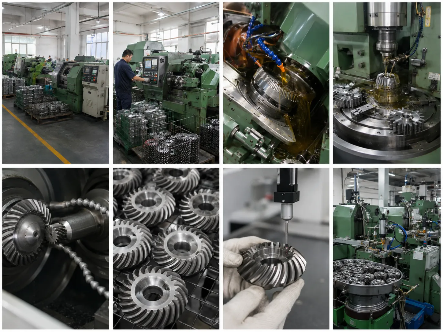
State-of-the-art CNC rack milling machines cut teeth without interruption on sections up to 2,000 mm; longer lengths through repositioning. All racks can be milled and matched for continuous travel accuracy.
Drilling and Tapping
CNC machining centres perform drilling, tapping, counter-boring, and intricate profile machining to your mounting hole pattern. All hole positions are verified dimensionally before dispatch.
Material Flexibility
Helical racks are available in mild steel, carbon steel, alloy steel, stainless steel, aluminium, brass, bronze, and engineering plastics in rectangular, square, and round cross-sections per customer specification.
Post-Process Options
Racks can be hardened, plated, coated, blasted, polished, or passivated per your specification. Tooth grinding to DIN 5-6 for precision applications is available on request.
Manufacturing Process
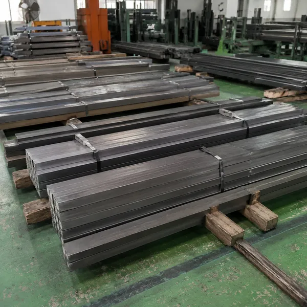
Step 1 — Raw Material
Raw material bar stock verified by spectrochemical analysis before production.
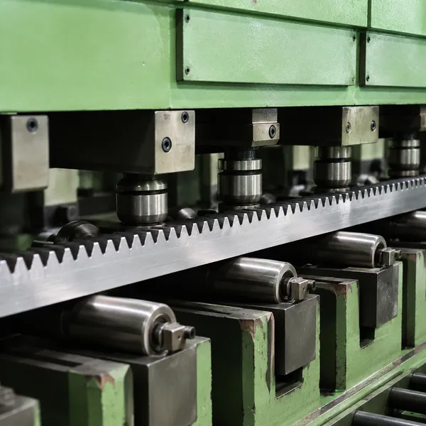
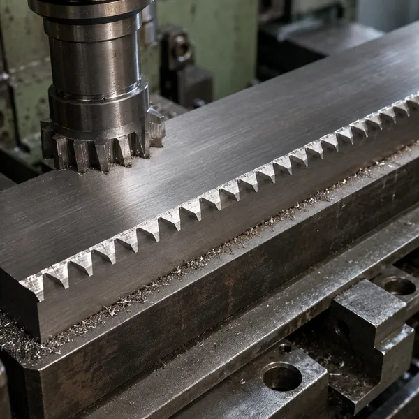
Step 2 — Tooth Cutting
Teeth cut on CNC rack milling or hobbing machine to specified module and pressure angle.
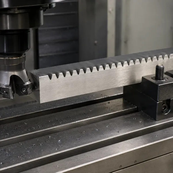
Step 3 — Deburring
Tooth-end burrs removed and edges chamfered to prevent handling damage and sharp corners.
Step 4 — Straightening / HT
Pressure straightening after tooth cutting; induction hardening or carburising where specified.
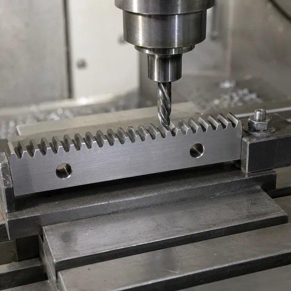
Step 5 — End Machining
End faces and mounting holes machined in CNC machining centre to drawing specification.
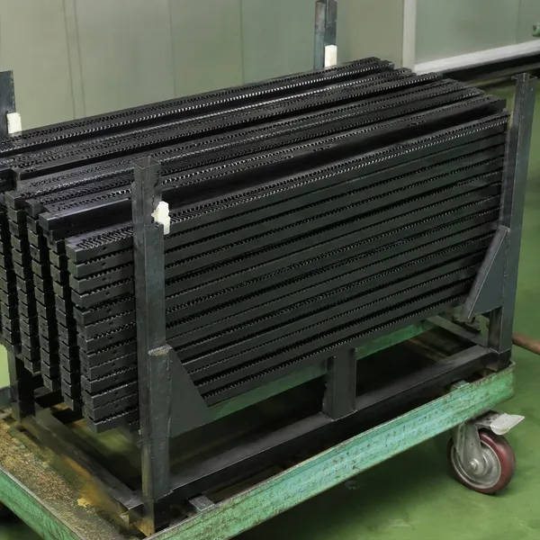
Step 6 — Surface Treatment
Black oxide, zinc plating, phosphating, or hard chrome applied per customer specification.
Key Production Equipment
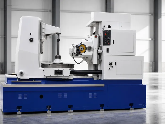
Gear Hobbing Machine
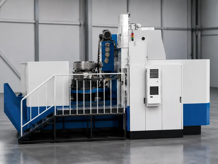
Gear Milling Machine
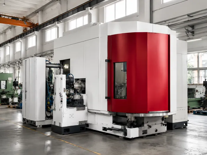
CNC Gear Grinding Machine
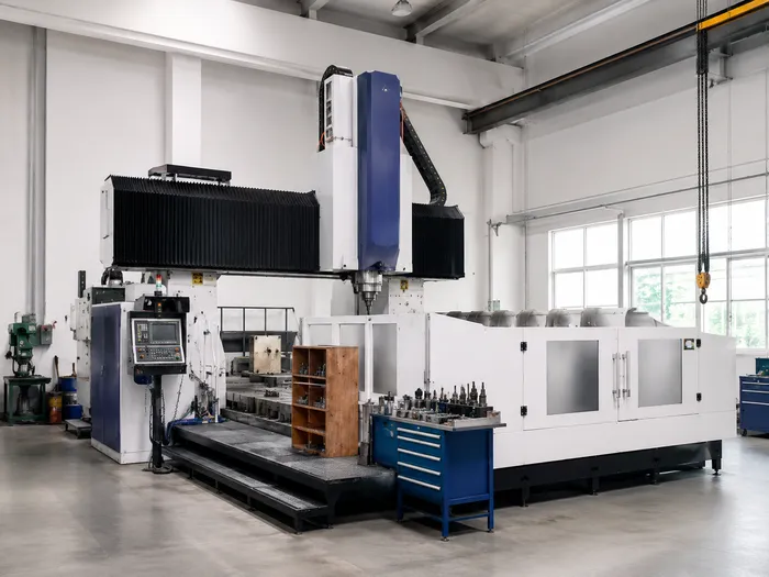
Gantry CNC Machining Centre
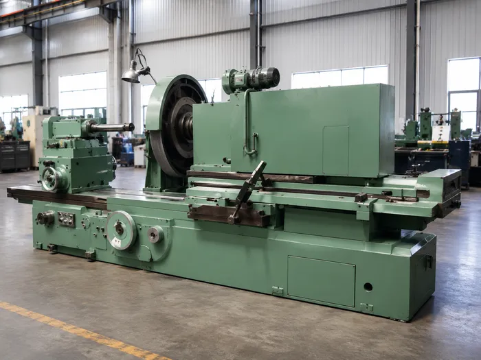
Internal Grinding Machine
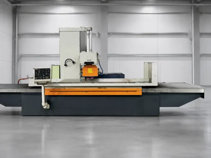
Planer Grinding and Turning
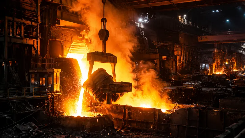
Applications by Industry







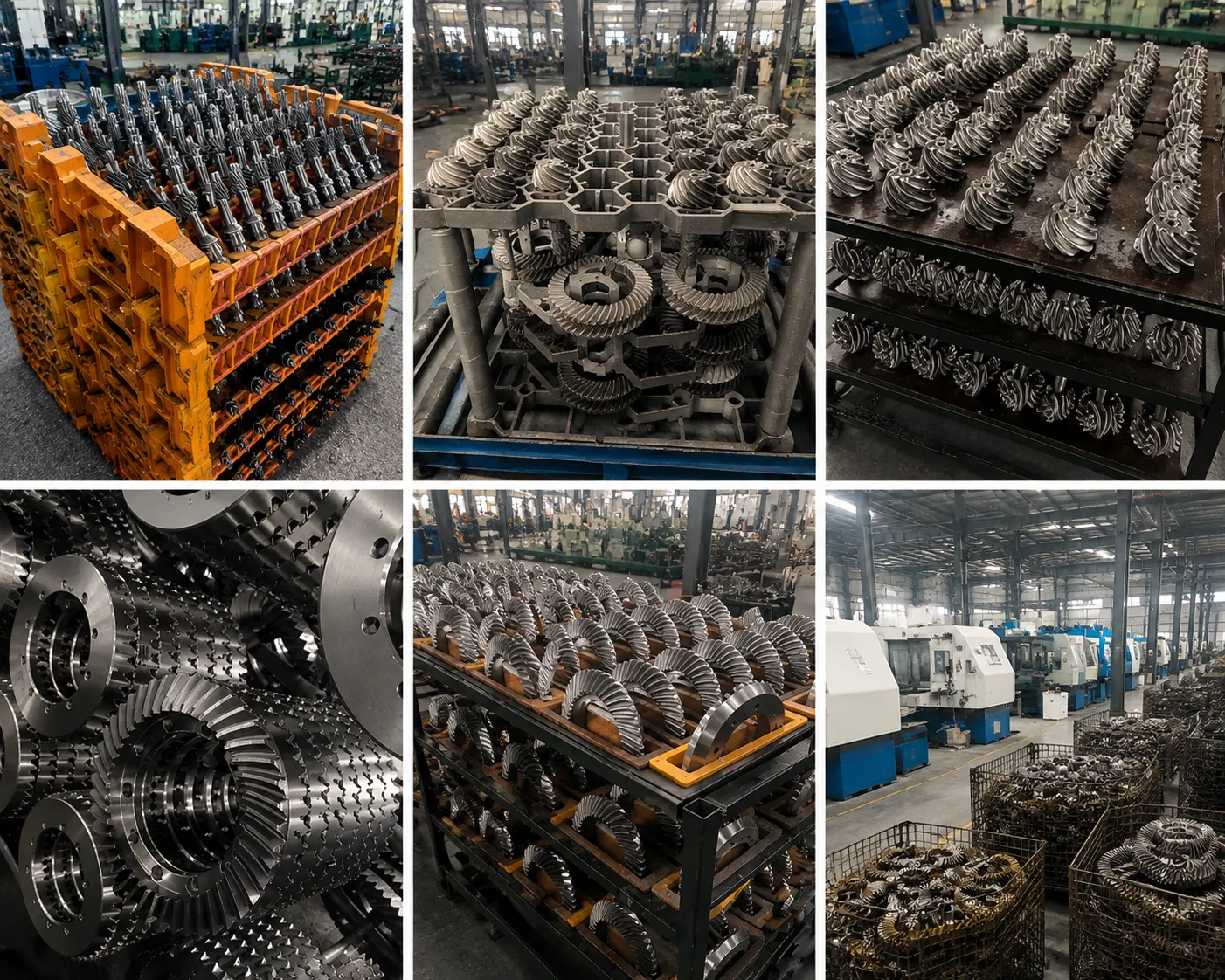
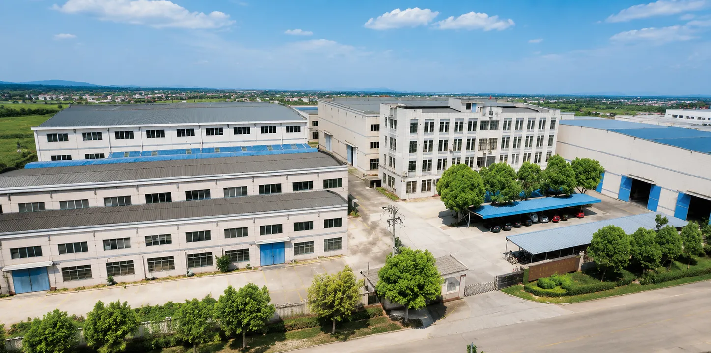
Quality Assurance and Production Facility
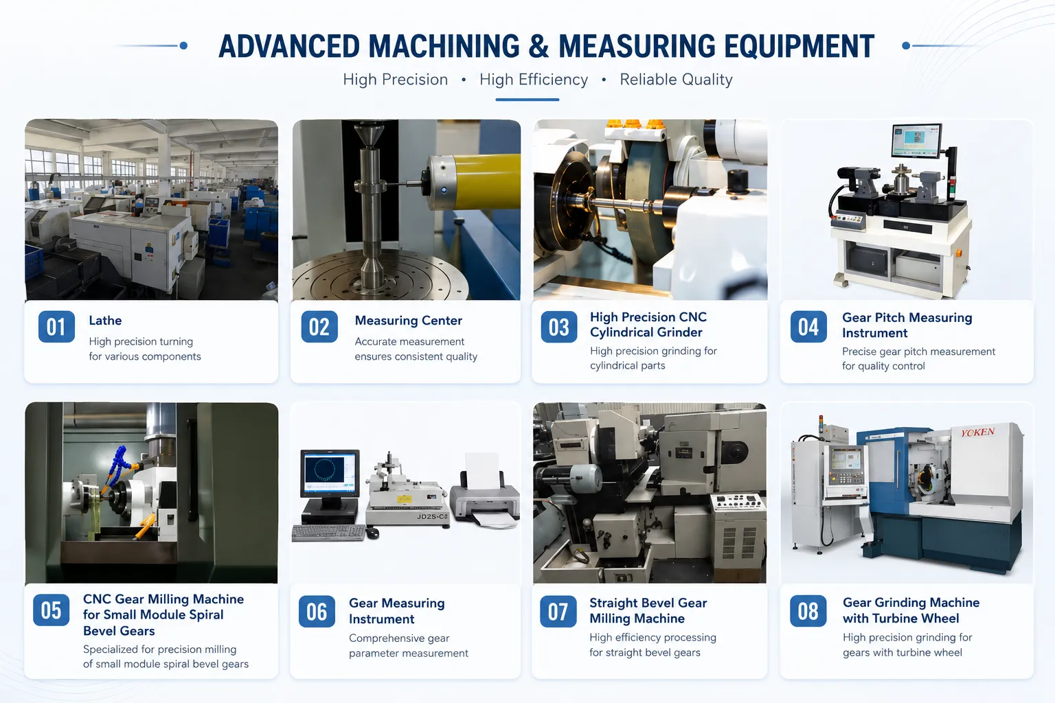
Precision Measurement Equipment
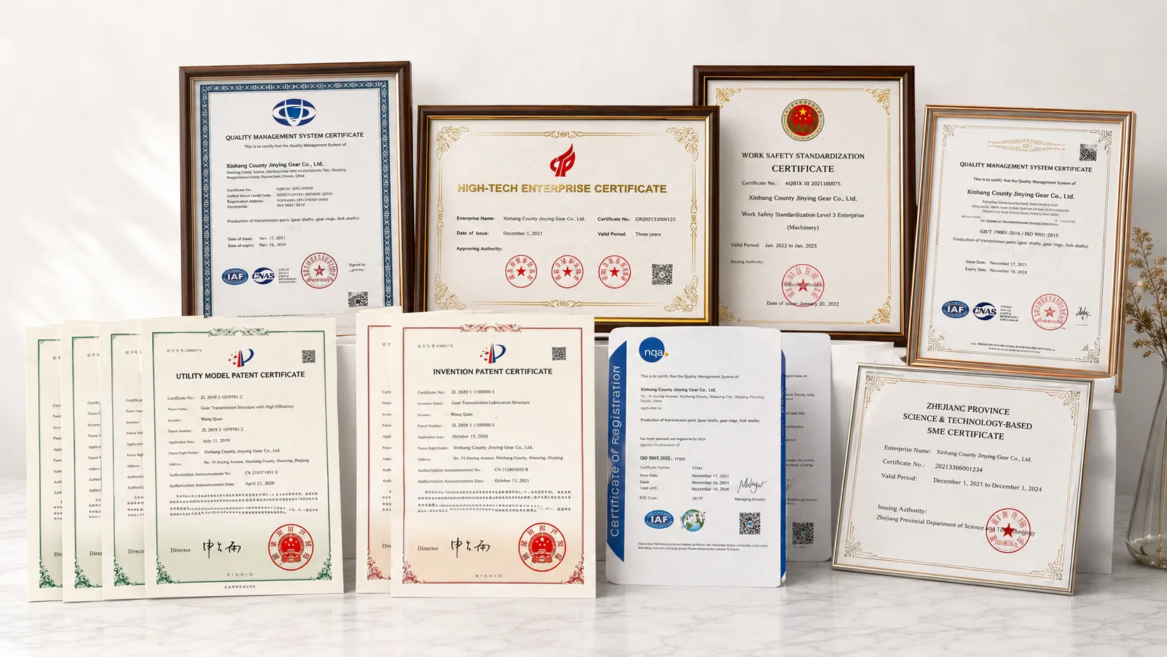
ISO 9001:2015 and Quality Certificates
CNC Gear Hobbing Machine
CNC Gear Grinding Machine
Every helical gear rack order is manufactured under ISO 9001:2015 and shipped with a complete documentation package: incoming material certificate with chemical composition, heat treatment time-temperature record, dimensional inspection report covering pitch error per 300 mm, tooth thickness, and face width, and a surface hardness test report at tooth flank and rack body. For precision ground helical racks, a CMM pitch deviation printout is included.
Precision Measurement and CMM Inspection
ISO 9001:2015 Certified
Related Gear Products
Helical racks require matched helical pinions and are often driven through reduction stages. The following product families are available from Ever-Power to complete your drive system from a single source.
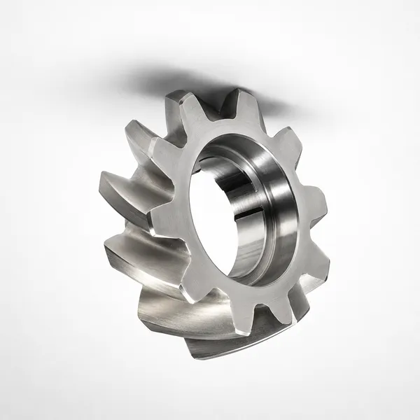
Ingranaggi elicoidali
Matched helical pinions for our rack range; helix hand and module must correspond to the rack specification.
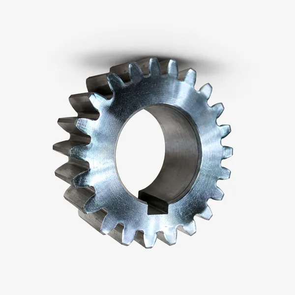
Ingranaggi cilindrici
Spur pinions for low-speed rack drives and as intermediate stages in the motor-to-pinion reduction train.
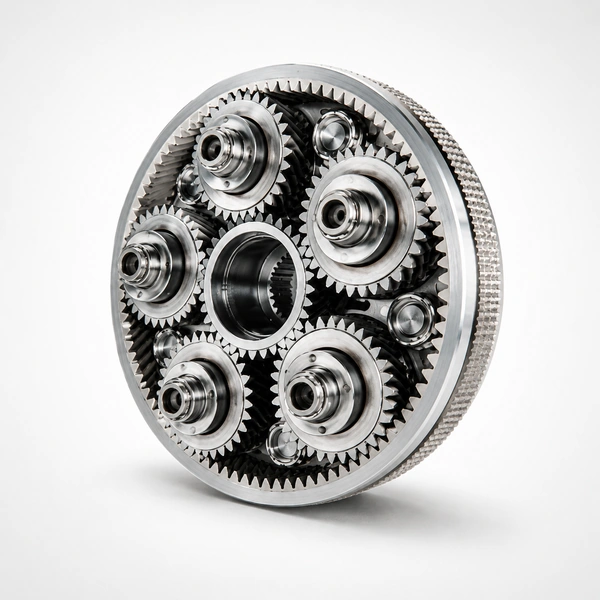
Planetary Gear Sets
Compact in-line servo reducers connecting motor to helical rack pinion. Helical planet versions match the rack drive noise profile.
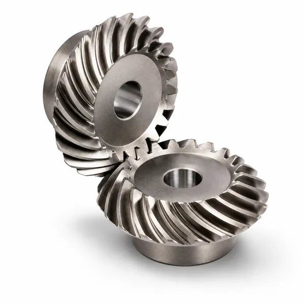
Ingranaggi conici
Right-angle input stages where the motor cannot be mounted in-line with the pinion shaft.
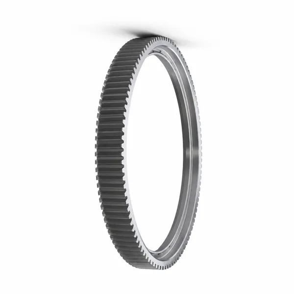
Corone dentate
Large-diameter ring gears for rotary drives often used alongside helical rack linear axes in multi-axis systems.
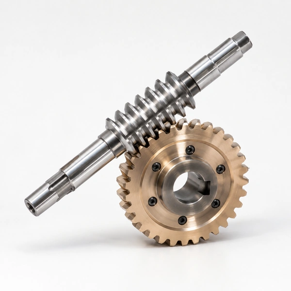
Worm Gear Wheels
Self-locking reducers for vertical helical rack axes that must hold position without a motor brake.
Browse the full gear rack range — including spur racks, ground precision racks, round racks, and application-specific rack products — on the Ever-Power main site. Matched plastic gear pinions are also available for light-duty and noise-sensitive helical rack applications.
Related Gear Products
Ever-Power manufactures the complete range of industrial gear types alongside gear racks. If your drive system requires matched pinions, reduction gears, or associated gear types, the following product families are available from the same source.
Ingranaggi cilindrici
Pinion gears matching our spur gear rack range; standard modules m0.5 to m20.
Corone dentate
Large-diameter internal or external ring gears for rotary and slewing drives.
Ingranaggi conici
Straight and spiral bevel gears for right-angle drives and gear motor input stages.
Ingranaggi elicoidali
Helical pinions for high-speed, low-noise rack drives and reduction stages.
Planetary Gear Sets
Compact in-line reducers paired to servo motors; output shaft connects to the rack pinion.
Worm Gear Wheels
Self-locking worm reducers for vertical rack axes holding position under gravity load.
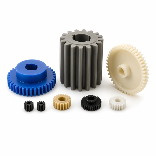
Plastic Gears
Nylon, POM, and polycarbonate pinion gears for light-duty, lubrication-free rack drives.
Domande frequenti
What helix angle should I specify for a helical gear rack?
The standard helix angle for Ever-Power helical racks is 19°31min42sec, which matches the most widely available helical pinions in servo gearhead catalogues from major brands. If your pinion is already specified at a different angle — 14°, 15°, or 45° are also common — the rack must match exactly. Mixing helix angles causes incorrect tooth contact and rapid wear. Specify your pinion helix angle at the enquiry stage and we will manufacture the rack to match; if no pinion is yet specified, the 19°31min42sec standard is the lowest-risk starting point.
Why does a helical rack generate axial thrust and how is it managed?
The angled tooth geometry that gives a helical rack its quieter mesh also creates a force component acting along the pinion shaft axis — the axial thrust. Its magnitude is the tangential rack force multiplied by the tangent of the helix angle. At 19°31min42sec, this is approximately 35% of the tangential force — significant enough to require an angular-contact ball bearing or a thrust bearing at the pinion shaft in addition to the radial bearing. The direction of thrust reverses with the direction of rack travel, so the bearing arrangement must react thrust in both directions. Angular-contact ball bearings in back-to-back (DB) arrangement are the standard solution for servo-driven CNC axis pinion shafts.
What is the pitch error specification and how does it affect positioning accuracy?
Pitch error is the deviation between the actual tooth spacing and the theoretical spacing, measured cumulatively over 300 mm. For JIS Grade 5 (the standard Ever-Power helical rack grade), pitch error ranges from 0.020 mm per 300 mm at M1 to 0.052 mm per 300 mm at M10. In a closed-loop servo system with encoder feedback on the motor, this pitch error is partially compensated by the control system through pitch error compensation tables. In an open-loop system, pitch error translates directly into positioning error. For applications requiring better than 0.05 mm positioning accuracy over long travel, specify precision-ground helical racks in JIS Grade 3 or better, and use a linear encoder on the machine rather than relying on rotary encoder-based position feedback alone.
Are you a trading company or manufacturer?
Ever-Power is a manufacturer. Our facility produces gear racks on a full set of CNC rack milling machines, gear hobbers, and gear grinders. We do not re-sell third-party products. All racks are manufactured, inspected, and documented in-house under ISO 9001:2015 before dispatch.
Can you produce custom helical racks from our drawing?
Yes. Submit your drawing in DXF, DWG, STEP, or PDF format and our engineering team will review feasibility, advise on any modifications required for producibility, and return a price and lead-time proposal. Prototype samples are available prior to production; sample cost is credited against the first production order above a minimum quantity threshold confirmed at the quotation stage.
What lubrication is required for helical gear rack drives?
For enclosed helical rack drives, ISO VG 220 gear oil with an EP additive is the standard starting point at pitch-line speeds below 10 m/s and operating temperatures between 10°C and 60°C. For high-speed servo gantries with automatic lubrication systems, ISO VG 68 way oil or a specific rack grease designed for automatic dispensers is used — the oil is metered at 0.1 to 0.5 ml per cycle so the tooth flanks remain coated without excess oil being flung onto guide rails or workpieces. At operating temperatures above 60°C or below 0°C, a synthetic PAO-based lubricant of the equivalent viscosity grade maintains its film thickness more reliably than mineral grades across the extended temperature range.
Request a Quotation for Helical Gear Racks
Send us your module, helix angle, length, material, and required precision grade — or attach your drawing. Quotation returned within two working days.
Informazioni aggiuntive
| Redattore |
|---|
Prodotti correlati
-
Round Gear Rack | Cylindrical Bar Rack, M1 Steel, Custom OEM Supply
-
Gear Rack for Rack Actuator | Valve, Gate and Damper Control, OEM Supply
-
Metric Gear Rack | Spur and Helical, M1-M32, Steel and Plastic OEM Supply
-
Gear Rack for Construction Elevator | Hoist Rack, M6-M10, OEM Supply
-
Gear Rack for Greenhouse | Ventilation, Irrigation and Shading Rack Systems
-
Gear Rack for Automobiles | Steering Rack, EPAS, OEM Replacement Supply
-

Ground Helical Gear Rack | DIN5-6 Precision, CNC Ground, OEM Supply
-
Gear Rack and Pinion | Spur, Helical, Ground and Custom OEM Supply
 Italian
  English
  Korean
  French
  Japanese