
Worm Gear Shaft (Worm Gear Drive Shaft) Customized Worm Shaft
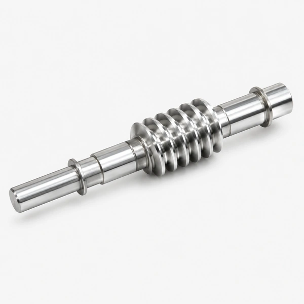
A worm gear shaft is the shaft that the worm gear is mounted on. Typically made of strong and durable steel to withstand high torque and wear. Supported by bearings to reduce friction and vibration. Transmits power from the motor to the worm gear. Two main types: straight (most common) and tapered. Module M1–M12 and custom. Materials: brass, C45 steel, stainless steel, copper, POM, aluminium, alloy. Surface treatment: zinc-plated, nickel-plated, black oxide, Geomet, Dacromet, passivation, phosphatising, powder coating, electrophoresis. Precision: DIN 6–9. Teeth treatment: hardened, milled or ground. Tolerance: 0.001–0.1 mm. Heat treatment: carburising, induction, flame, nitriding. Lubrication every 1,000–2,000 hours. Sample 20 days; bulk 25 days. T/T, L/C.
Product Overview
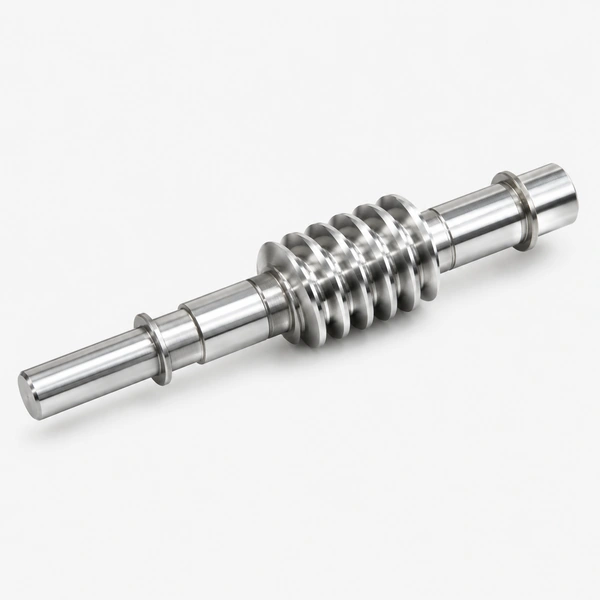
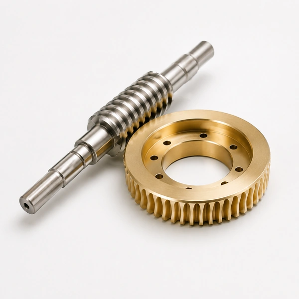
A worm gear shaft — also called a worm gear drive shaft or customized worm shaft — is the shaft on which the worm gear is mounted, or the shaft that is the worm itself (in integral worm shaft designs). It is typically made of strong and durable material, such as C45 steel, alloy steel, or stainless steel, to withstand the high torque and wear that is associated with worm gears. The worm gear shaft is supported by bearings to reduce friction and vibration. The worm gear shaft is the power transmission backbone of the worm gear assembly: it transmits the power from the motor to the worm gear and provides the support and alignment that the worm gear needs to operate properly.
Korea Ever-Power manufactures customised worm gear shafts in M1 to M12+ — straight and tapered types — in steel, stainless steel, brass, copper, POM, aluminium, and alloy. Finish: DIN 6–9 precision, 0.001–0.1 mm tolerance. Surface treatments including zinc-plated, nickel-plated, black oxide, and more. Lead time: 20 business days sample, 25 days bulk. Lubrication every 1,000–2,000 hours.
There are two main types of worm gear shafts: straight (the most common, for straight-line worm rotation) and tapered (for curved-line worm rotation). The size is determined by the worm gear size and the torque requirement — the shaft must be strong enough to resist bending and torsion without deflection that would affect the worm's mesh accuracy and contact pattern.
Technical Specifications
| Worm Gear Shaft — Product Specification | |
|---|---|
| Model / Module | M1, M2, M3, M4, M5, M8, M12 — and custom |
| Material | Brass, C45 steel, stainless steel, copper, POM, aluminium, alloy steel |
| Surface Treatment | Zinc-plated, nickel-plated, passivation, oxidation, anodisation, Geomet, Dacromet, black oxide, phosphatising, powder coating, electrophoresis |
| Standard | ISO, DIN, ANSI, JIS, BS — and non-standard |
| Precision Grade | DIN 6, DIN 7, DIN 8, DIN 9 |
| Teeth / Thread Treatment | Hardened, milled, or ground |
| Tolerance | 0.001 mm – 0.01 mm – 0.1 mm |
| Fine | Shot/sandblast, heat treatment, annealing, tempering, polishing, anodising, zinc-plated |
| Shaft Types | Straight (standard); tapered |
| Heat Treatment | Carburising, induction, flame, nitriding |
| Lubrication Interval | Every 1,000–2,000 hours of operation |
| Confezione | Plastic bag + cartons or wooden packing |
| Payment Terms | T/T, L/C |
| Sample Lead Time | 20 business days |
| Bulk Lead Time | 25 business days |
Worm Gear Shaft Design Features
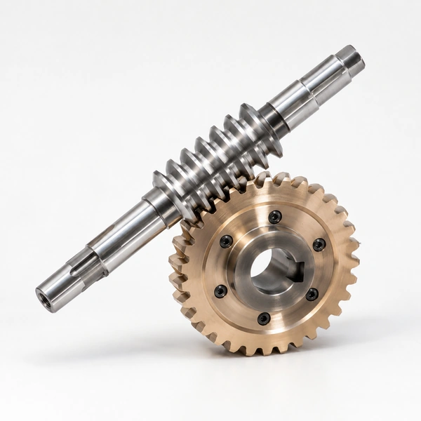
The design features of a worm gear shaft are determined by four primary factors: the size and type of worm gear, the torque to be transmitted, the operating environment, and the target cost. The following design parameters are specified for each customised worm gear shaft produced by Korea Ever-Power:
Material
The worm shaft material must withstand the combined torsional and bending stress produced by the worm tooth forces, plus the axial thrust force reacted through the shaft to the axial bearings. Standard worm shafts use C45 steel (medium carbon, quenched and tempered to 220–260 HB). High-torque or high-cycle worm shafts use case-hardened alloy steel (20CrMnTi, 42CrMo) with surface hardness HRC 58–62 and ground thread surface. Stainless steel worm shafts are selected for corrosive environments. POM or aluminium worm shafts for light-duty low-load miniature drives.
Diameter and Length
The shaft diameter is sized to limit torsional and bending deflection to values that maintain the correct worm-to-worm-wheel contact pattern. Excessive shaft deflection shifts the contact pattern to one end of the worm wheel face, concentrating the load and accelerating wear. The shaft length between bearing supports should be minimised to reduce bending moment — long unsupported spans are the most common source of shaft deflection and premature bearing failure in worm gear drives.
Keyway / Spline
Where the worm is a separate gear mounted on a shaft (as opposed to integral worm shaft designs), the worm is connected to the shaft by keyway or spline. Keyway connections are standard for moderate torques; involute spline connections are used for high-torque or reversing-load applications where the torque level or cyclic loading would cause fretting corrosion in a key-and-keyway joint. Korea Ever-Power machines keyways and splines to DIN standards as standard on all worm gear shafts where specified.
Surface Treatment
The worm thread surface finish directly determines the worm gear efficiency and wear rate. Ground worm threads (Ra 0.4–0.8 µm) are standard for industrial worm drives — the ground thread reduces the friction coefficient at the mesh, improving efficiency by 5–15% compared with milled threads. For outdoor or wet environments, zinc-plated, nickel-plated, or black oxide surface treatment of the worm shaft (non-thread areas) is specified to prevent corrosion at the bearing journal surfaces and keyway.
Bearings
The worm shaft is supported by bearings at both ends. The worm shaft experiences both radial (from the worm tooth forces) and axial (from the worm tooth helix angle component) bearing loads simultaneously. The standard solution is angular contact ball bearings or tapered roller bearings in paired arrangement (DB or DF) to handle both load components. Bearing selection must account for the combined load at the specific lead angle and input power. Korea Ever-Power specifies the correct bearing arrangement for each customised worm gear shaft drive delivered.
Straight vs Tapered Worm Shaft
Straight worm shaft: The most common type. The worm thread pitch diameter is constant along the worm length. Produces a linear tooth engagement path. Used in all standard worm gear drives: conveyor reducers, valve actuators, lifting drives, and indexing drives.
Tapered worm shaft: The worm thread pitch diameter varies along the worm length. This geometry produces a progressive increase in the effective pressure angle from one end of the worm to the other, which can be used to adjust the mesh tightness (backlash control) by shifting the worm axially. Used in precision worm gear drives where adjustable backlash control is required — such as CNC rotary tables and precision indexing worm drives.
Worm Gear Shaft Design Process
Korea Ever-Power's worm gear shaft design process follows a structured six-step sequence to ensure that each customised worm shaft meets the application's torque, speed, life, and environmental requirements before manufacture:
| Step | Action | Key Considerations |
|---|---|---|
| 1 | Define worm gear size and type | Module, number of starts, number of wheel teeth, centre distance, lead angle, helix direction |
| 2 | Determine torque | Input torque from motor; output torque (input × ratio × efficiency); peak and cycling torque for fatigue analysis |
| 3 | Consider operating environment | Temperature range, humidity/corrosion exposure, contamination, required IP rating, lubrication type and accessibility |
| 4 | Consider cost and lead time | Material grade, heat treatment depth, surface finish grade, quantity — all affect cost and lead time |
| 5 | Select material, size, shape, finish, bearings | Safety factor ≥ 2.5 on bending and torsion; surface hardness HRC 58–62 for high-duty; bearing life L10 ≥ 20,000 hrs minimum |
| 6 | Verify and manufacture | FEA confirmation of deflection; CMM inspection of thread accuracy; contact pattern test against mating worm wheel before shipment |
Worm Gear Shaft Lubrication and Maintenance
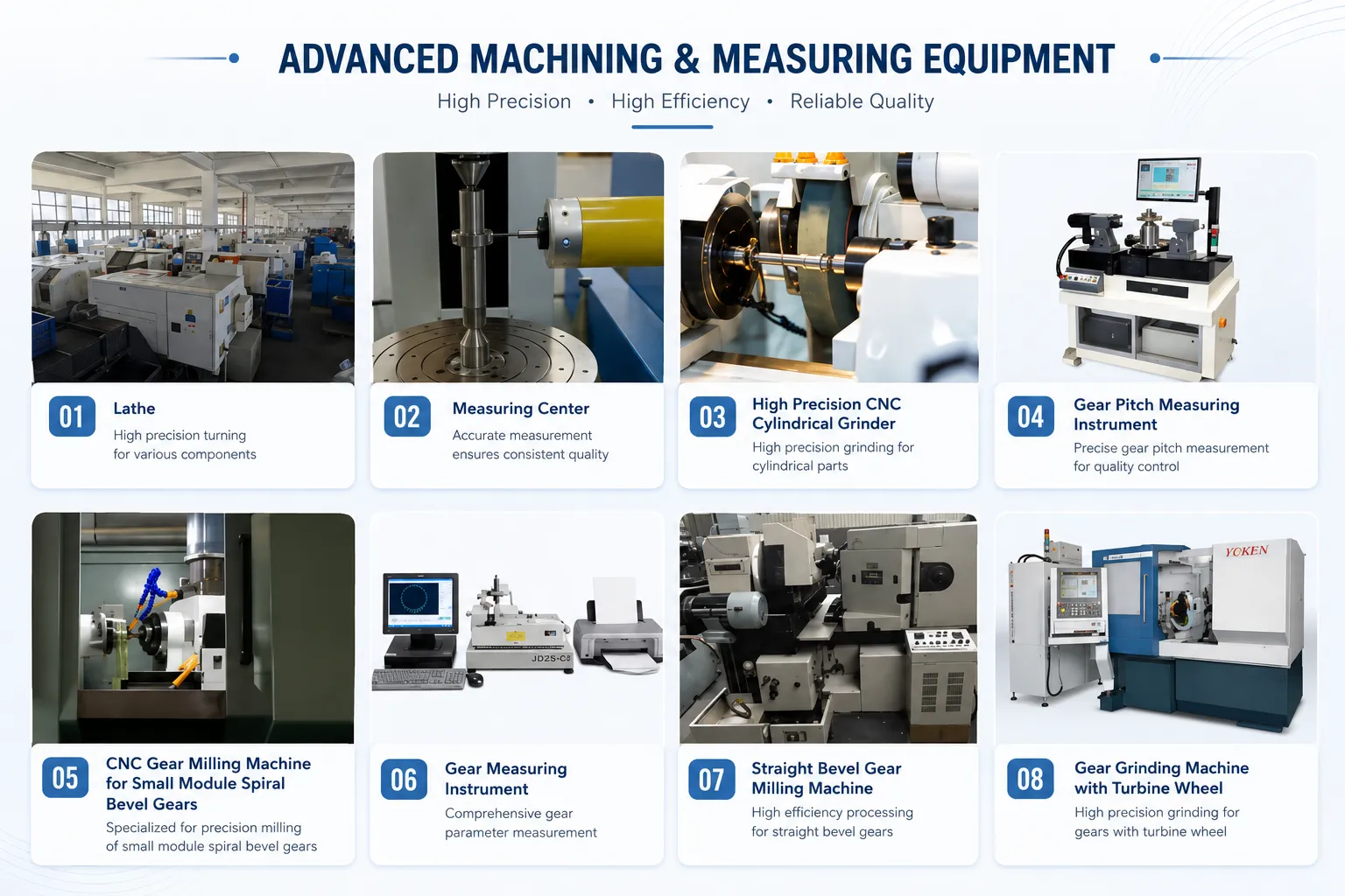
Worm gear shafts require regular lubrication and maintenance to extend service life and prevent premature failure. The worm gear mesh's high sliding contact velocity between the worm thread and worm wheel tooth requires good lubrication film maintenance at all times — unlike rolling-contact gear types, the worm gear mesh relies entirely on hydrodynamic or elasto-hydrodynamic oil film to separate the metal surfaces and prevent adhesive wear (scuffing).
Lubricant Selection
Use high-quality worm gear oil — specifically formulated with EP (extreme pressure) and anti-wear additives for worm gear sliding contact. Standard viscosity: ISO VG 220 for ambient temperatures 10–40°C; ISO VG 460 for higher temperatures or heavily loaded worm drives. Avoid general-purpose gear oils not formulated for worm gears — they lack the friction modifier that reduces the sliding contact friction coefficient and protects the bronze worm wheel from adhesive wear.
Lubrication Interval
Lubricate worm gear shafts every 1,000–2,000 hours of operation. For sealed worm gearbox units (oil bath lubrication), change the oil at the first interval after 500 hours to remove run-in wear particles, then at the standard interval thereafter. For open worm gear drives lubricated with grease, reapply grease every 500 hours and inspect the worm thread surface for wear each application. High-temperature or high-duty-cycle applications require shorter intervals — consult Korea Ever-Power for application-specific guidance.
Regular Inspection
Inspect worm gear shafts regularly for: thread surface wear (scoring, pitting, or polishing beyond the run-in stage); shaft cracks at stress concentration points (thread root, keyway, shoulder fillets); bearing journal wear; and axial play increase (indicating bearing wear). If scoring or pitting is found on the worm thread surface, replace the worm shaft — continued operation with a damaged thread surface will rapidly destroy the bronze worm wheel and is uneconomical.
Correct Lubricant Application
Apply lubricant evenly to all worm thread surfaces and bearing journals. For oil-bath lubricated worm gearboxes, the oil level should cover the bottom of the worm gear (worm below) or the bottom of the worm wheel (worm above arrangement). For worm-above arrangements, forced lubrication or oil splash from the worm wheel is required to wet the worm thread, since gravity will not carry oil upward to the worm mesh. Korea Ever-Power's worm gear drive shaft is delivered with application and lubrication guidance.
Applications of Worm Gear Shafts
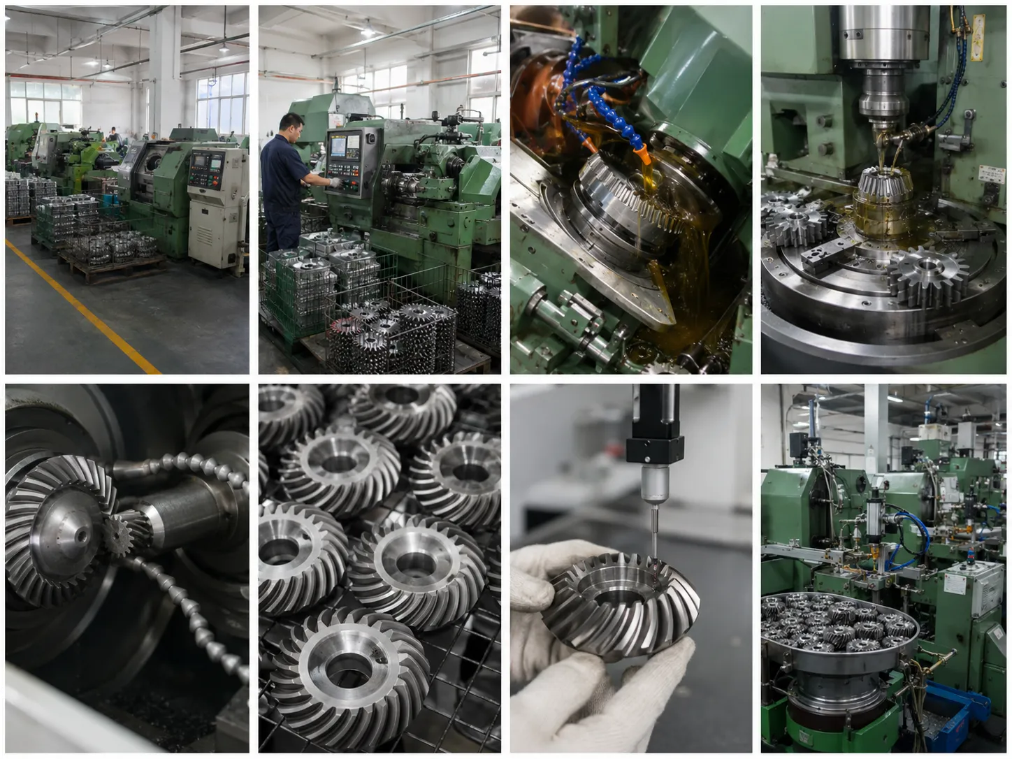
Machine Tools
High-precision ground worm gear shafts M3–M8 in lathe and milling machine table feed worm drives. The shaft must resist bending deflection under the heavy table loads while maintaining the worm thread position accuracy required for smooth, backlash-free table movement. Alloy steel, case-hardened and ground worm shafts are standard for machine tool applications.
Elevators and Lifting Drives
Large-module worm gear shafts M8–M12 in elevator drive worm gearboxes and material lifting drive reducers. The worm shaft in elevator applications must provide high torsional stiffness (to avoid oscillation of the suspension cable during starting and stopping) and reliable self-locking (to prevent the cabin from descending if the motor fails). C45 or 42CrMo alloy steel, quenched and tempered, ground thread.
Conveyors and Packaging Machinery
Standard C45 worm gear shafts M4–M8 in conveyor drive worm gearboxes and packaging machinery right-angle drives. Continuous operation at moderate loads; oil bath lubrication standard. The compact right-angle output of the worm shaft drive allows the motor to mount parallel to the conveyor frame while the output shaft drives the conveyor perpendicular — the arrangement that drives the majority of industrial conveyor installations worldwide.
Robotics
Precision worm gear shafts M1–M4 in robotic wrist and arm joint drives. The compact size and self-locking of the worm shaft drive allows robotic joints to hold position without brake or motor power — reducing energy consumption and eliminating the noise of continuously-energised brakes. Stainless steel or alloy steel worm shafts for cleanroom and food-safe robot environments.
Wind Turbines and Solar Panels
Large alloy steel worm gear shafts M8–M12 in wind turbine nacelle yaw drives and solar tracker azimuth drives. These are 20–25 year service life applications operating in outdoor environments with temperature ranges of −40°C to +70°C — requiring high-grade alloy steel, full surface corrosion protection, and sealed bearing arrangements with extended grease replenishment intervals.
Textile and Food Processing Machinery
Stainless steel worm gear shafts M2–M6 in textile machine loom control drives and food processing machinery conveyor and portioning drives. Stainless steel is required for washdown environments in food processing and for the chemical resistance required in textile dyeing machine applications. FDA-compliant food-grade lubricant compatibility required for food contact zones.
Frequently Asked Questions
What is the difference between a worm gear shaft and a worm drive shaft?
The terms are used interchangeably. "Worm gear shaft" refers to the shaft on which the worm is mounted (if the worm is a separate gear) or the integral shaft that has the worm thread machined directly into it (integral worm shaft). "Worm gear drive shaft" emphasises the power transmission function — this shaft transmits the drive power from the motor to the worm gear mesh. Korea Ever-Power's customised worm shaft covers both configurations.
What materials are worm gear shafts made from and how do I choose?
C45 steel (quenched and tempered) is the standard for moderate loads; 20CrMnTi or 42CrMo alloy steel (case-hardened, HRC 58–62, ground thread) for high loads or long life; stainless steel for corrosive/washdown environments; POM or aluminium for miniature, light-load applications. The choice is driven by the application load, environment, and cost — send the application requirements and Korea Ever-Power will recommend the appropriate material.
How do you maintain a worm gear shaft to extend its service life?
Lubricate every 1,000–2,000 hours with high-quality worm gear oil (ISO VG 220–460 with EP additives). Inspect the thread surface, shaft condition, and bearing axial play at each lubrication interval. Replace oil at the first 500-hour interval in sealed gearboxes to remove run-in wear particles. Keep the operating temperature within the oil's viscosity specification — overheating (typically above 80°C oil sump temperature) indicates insufficient lubrication or overloading. Contact Korea Ever-Power for application-specific lubrication guidance.
Customer Reviews
"We build industrial worm gearboxes for conveyor drives and source M8 alloy steel worm gear shafts from Korea Ever-Power. Thread accuracy to DIN 7 confirmed at incoming inspection using our worm measurement rig — pitch error and helix angle error both within tolerance. Contact pattern with our tin bronze worm wheel: 78% face width, centred. No thread wear issues after 12 months continuous operation at 2.5 m/s sliding velocity."
Kim Do-hyeon | Worm Gearbox Production Engineer, Incheon Power Drives Co. · Q1 2026
"We needed stainless steel worm gear shafts M4 for a food processing line with daily hot washdown. Korea Ever-Power supplied SS304 worm shafts with ground thread surface and passivated bearing journals. No corrosion in 18 months of daily washdown. FDA food-grade lubricant compatible — confirmed in writing from Korea Ever-Power before we placed the order."
Lee Byeong-jun | Food Processing Equipment Engineer, Gyeonggi Food Machinery Co. · Q3 2025
"We develop precision robotic wrist joint drives and source M2 alloy steel worm gear shafts from Korea Ever-Power. The DIN 6 precision and 0.001 mm tolerance on the shaft journals gives us the low backlash we need for wrist positioning accuracy. Self-locking verified at our torque test bench — joint holds target angle within ±0.02° with motor de-energised. Sample delivered in 19 business days."
Park Seong-hyeon | Robotic Actuator Engineer, Daejeon Precision Robotics Co. · Q2 2026
Related Products
Request a Quotation for Customised Worm Gear Shafts
M1–M12+, straight or tapered, C45 / alloy steel / SS / POM. DIN 6–9 precision. Ground thread available. Sample 20 days; bulk 25 days. Send drawing or specification to begin.
Informazioni aggiuntive
| Editor |
|---|
Prodotti correlati
-
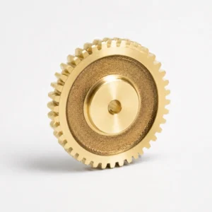
Brass Worm Wheel – M0.5, 20T, Complete Set with Worm Shaft
-
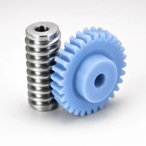
Plastic Worm Gears – POM/Nylon, M0.2-M2.0, Low Noise
-
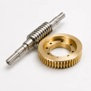
Worm and Wheel – High Precision Brass, M3-M12, 20:1-300:1
-
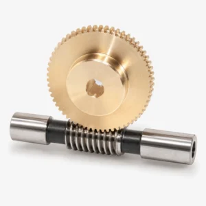
Customized Worm Gear Set – OEM, All Materials, No MOQ
-
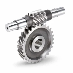
Stainless Steel Worm Gear for CNC Machinery – DIN 5-7, M1-M4
-
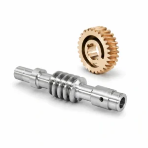
Alloy Steel Worm And Worm Gear for Auto Parts – M0.2-M2.2, ODM
-
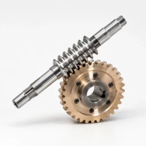
Cylindrical Worm Wheel – ISO/DIN, Line Contact, All Materials
-
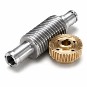
Duplex Worms Gear – Adjustable Backlash, Zero Backlash Precision
 Italian
  English
  Korean
  French
  Japanese