
Spiral Bevel Gears – Helical Bevel Gear, Custom OEM Supply
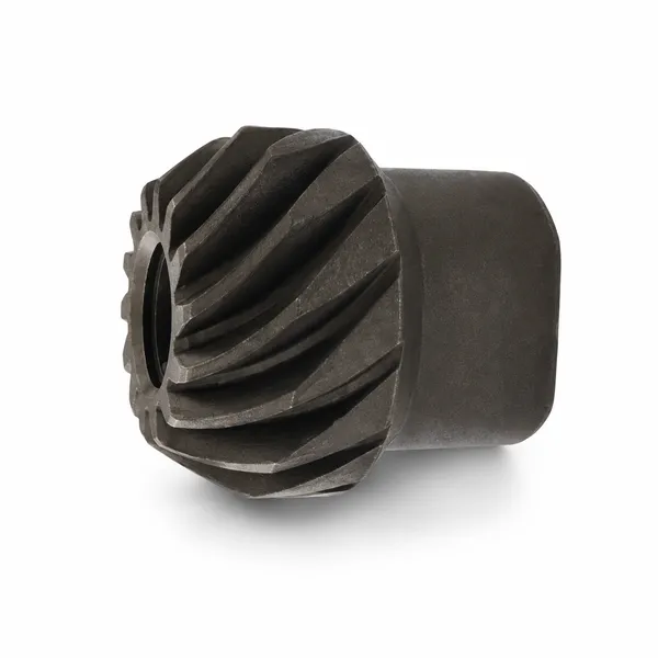
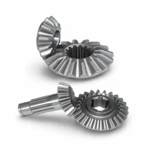
Korea Ever-Power spiral bevel gears (helical bevel gears) transmit power between intersecting shafts with lower noise and vibration than straight-tooth alternatives. Curved helical teeth allow progressive tooth engagement and a larger contact area, giving spiral bevel gears higher load capacity and better fatigue life in automotive differentials, industrial gearboxes, mining drives, and high-speed printing equipment. Matched pairs, OEM drawings accepted, material and hardness certification included.
Product Overview
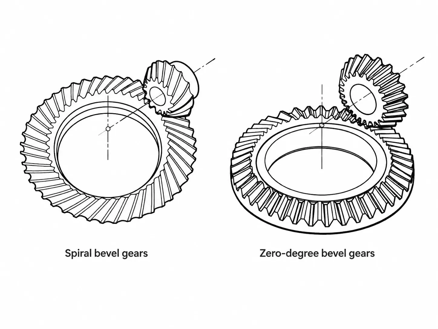
A spiral bevel gear — also referred to as a helical bevel gear — is a bevel gear whose teeth are cut at a curved oblique angle across the cone face rather than running straight from toe to heel. This curvature means each tooth enters mesh progressively at one end and exits at the other, so the load transitions smoothly from tooth to tooth rather than landing instantaneously along the full flank. The result is lower impact loading, quieter operation, and the ability to transmit more torque within the same outer diameter compared with a straight bevel gear of identical module.
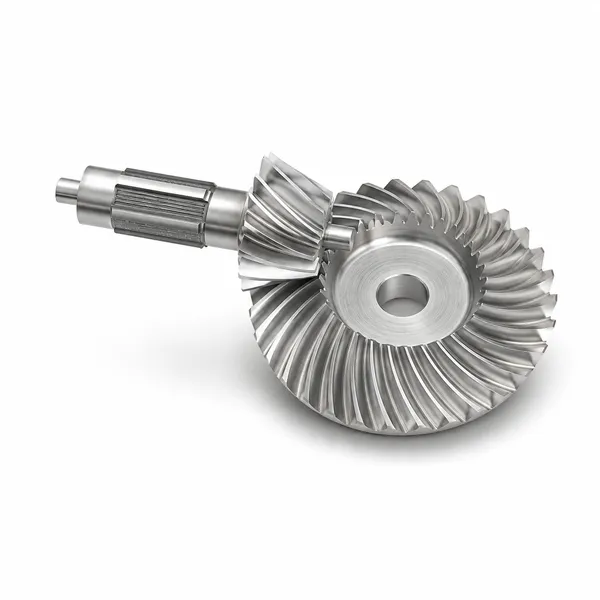
Korea Ever-Power spiral bevel gears are produced from alloy steel blanks through a combination of blank forging or bar stock preparation, hobbing or face-milling on dedicated bevel gear cutting machines, case-hardening or through-hardening, and tooth grinding or lapping to the final accuracy class. The hand of spiral — left-hand or right-hand — determines the direction of axial thrust under load, and both hands are available as matched pairs. A spiral bevel gear set is always supplied and should always be replaced as a matched pair, because the ring gear and pinion are lapped together during production and the contact geometry is optimised for that specific pairing.
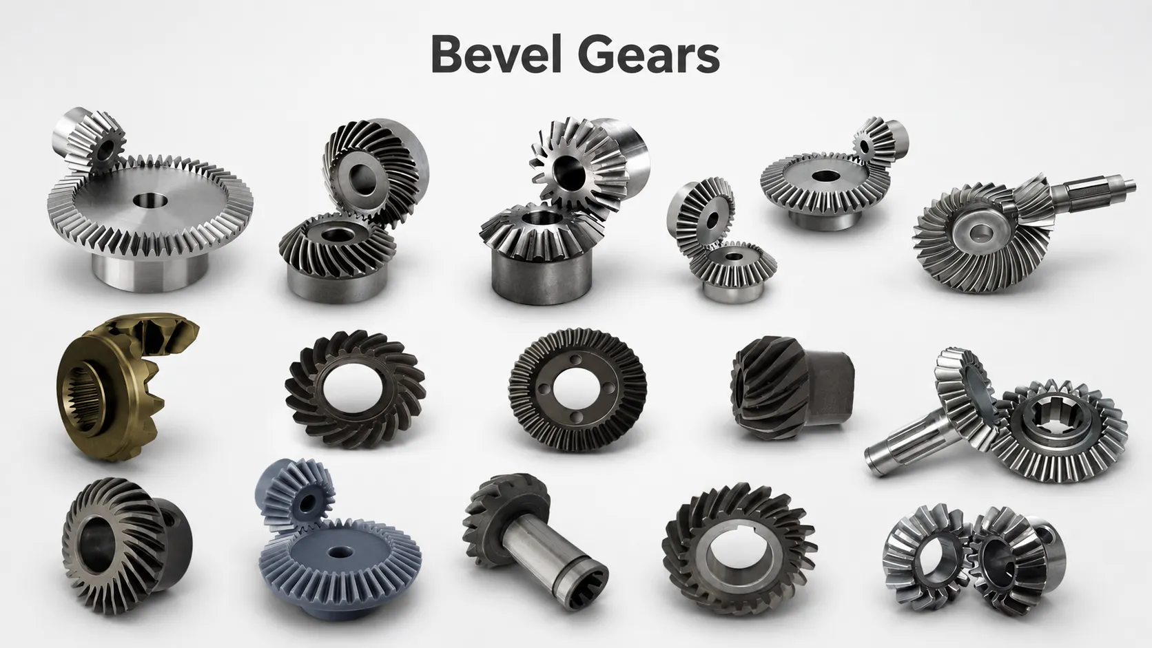
The most widespread application is the vehicle differential, where the drive from a longitudinal propeller shaft must be turned through 90 degrees to reach the wheel axle. Beyond automotive drivetrains, helical bevel gears are the standard choice in industrial speed reducers, high-speed printing presses, aerospace auxiliary drives, mining conveyor heads, and pharmaceutical packaging lines — any application where a right-angle direction change is combined with a requirement for low noise or high continuous load. The full bevel gear range from Korea Ever-Power includes straight bevel, miter, zero-degree, and hypoid variants alongside the spiral type.
Technical Specifications
The parameters below describe the general production capability for Korea Ever-Power spiral bevel gears. All specific values — module, tooth count, spiral angle, bore dimensions, and heat treatment depth — are confirmed against your drawing or sample at the quotation stage before order placement.
| Parameter | Typical Range / Options |
|---|---|
| Gear Type | Spiral bevel gear (helical bevel gear), matched ring-and-pinion pairs |
| Module | Per customer drawing or standard series; confirmed at quotation |
| Spiral Angle | Typically 35° mean spiral angle; other angles per drawing |
| Pressure Angle | 20° standard; other angles per customer specification |
| Hand of Spiral | Left-hand or right-hand; always supplied as matched pairs |
| Shaft Intersection Angle | 90° standard; other angles per drawing |
| Gear Ratio | Up to approximately 10:1 per stage; confirmed with enquiry |
| Outer Diameter | Small to large; confirmed against drawing at quotation |
| Material (Common) | 20CrMnTi, 20CrNiMo, 42CrMo, 40Cr, 45# steel |
| Material (Optional) | 304 / 316 stainless steel, cast iron, custom alloy per drawing |
| Heat Treatment | Carburising & quenching, induction hardening, through-hardening, nitriding |
| Tooth Finishing | Lapping (standard); tooth grinding available for high-accuracy grades |
| Machining Standard | AGMA, DIN, JIS, GB; customer drawings accepted |
| Surface Treatment | Phosphating, black oxide, zinc plating, as-machined |
| Efficiency per Stage | Typically 96% – 98% depending on accuracy, ratio, and operating conditions |
| 認証 | ISO 9001:2015; material cert and hardness report included with each order |
Advantages and Limitations of Spiral Bevel Gears
Why engineers specify spiral bevel
The curved tooth geometry gives spiral bevel gears a set of performance characteristics that straight bevel gears cannot match at equivalent size and module:
- Progressive tooth engagement — load transfers smoothly from tooth to tooth, eliminating the impact-style loading of a straight bevel at each mesh cycle. This is the primary reason spiral bevel gears run quieter and with less vibration at the same pitch-line speed.
- Higher contact ratio — more teeth are simultaneously in mesh at any instant, distributing the load across a larger total contact area. This allows higher torque capacity within the same outer diameter.
- Better fatigue life — lower contact stress per tooth and lower bending stress at the root both extend the working life against pitting and tooth-root fatigue compared with a straight bevel gear of the same size.
- Higher operating speed — the progressive engagement that reduces noise also allows higher pitch-line speeds without the vibration levels that limit straight bevel gears. High-speed printing and aerospace auxiliary drives rely on this.
- Less heat generation — lower sliding losses at the tooth flanks mean the gear set runs cooler, which reduces oil cooling requirements and extends lubricant service intervals.
Design constraints to plan for
- Matched-pair replacement — ring gear and pinion are lapped together during manufacture; the contact geometry belongs to that specific pair. Replacing one half without the other destroys the optimised contact pattern and shortens service life.
- Axial thrust load — the helical tooth geometry generates an axial force component whose direction depends on the hand of spiral and rotation direction. Bearings and housings must be designed to absorb this thrust; it is a design input, not an afterthought.
- Precision mounting requirement — spiral bevel gears are sensitive to deviations in mounting distance. Incorrect mounting distance shifts the contact pattern, raising local stress and reducing gear life. Assembly must hold mounting distance to the design tolerance.
- Not suited for very high reduction ratios at speed — spiral bevel gears are efficient up to approximately 10:1 per stage under normal operating conditions. Where a higher ratio combined with high speed is required, a hypoid stage or a multi-stage arrangement is the better solution.
Spiral Bevel Gear vs. Hypoid Gear — Key Differences
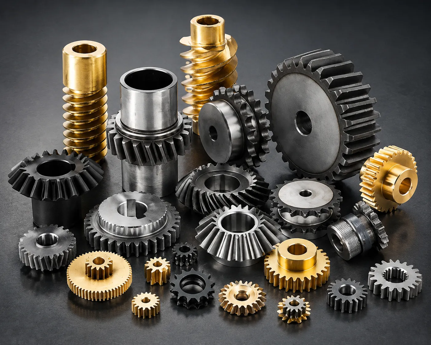
A hypoid gear is geometrically similar to a spiral bevel gear but with one critical difference: the axes of the ring gear and pinion do not intersect. The pinion axis is offset below (or above) the ring gear axis by a defined hypoid offset distance. This offset changes the tooth geometry from a conical shape to a hyperboloid of revolution, which is where the name comes from.
| Criterion | Spiral Bevel Gear | Hypoid Gear |
|---|---|---|
| Axis arrangement | Axes intersect at a point | Axes offset — do not intersect |
| Tooth shape | Conical pitch surface | Hyperboloid pitch surface |
| Efficiency per stage | ~96% – 98% | ~90% – 96% (higher sliding) |
| Ratio range | Up to ~10:1 | Up to ~25:1 |
| Noise | Quiet | Quieter (more tooth overlap) |
| Strength | High | Up to ~30% higher (larger contact) |
| Lubrication | Standard EP gear oil | Requires hypoid-rated EP oil (higher sliding) |
| Typical application | Industrial gearboxes, aerospace, printing | Automotive rear axle, heavy truck differentials |
For most industrial applications where the shafts can be arranged to intersect at 90°, the spiral bevel gear is the preferred choice on grounds of higher efficiency and simpler lubrication requirements. The hypoid arrangement is chosen when the axis offset is necessary for packaging reasons — for example, lowering the propeller shaft in a passenger car to reduce the tunnel height in the vehicle floor — or when the ratio requirement exceeds what a spiral bevel stage can deliver efficiently.
Manufacturing Process
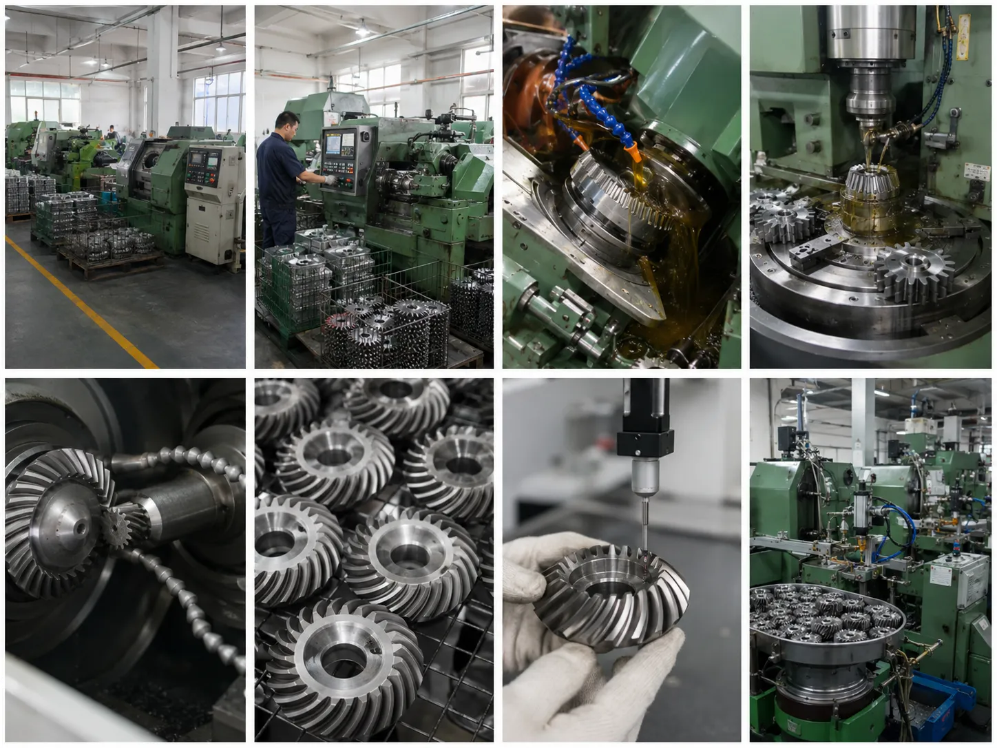
Korea Ever-Power produces spiral bevel gears through the following sequence. Each stage is tracked with process records that accompany the finished order documentation.
- Blank preparation — forged or bar-stock blank is rough-machined to pre-gear dimensions. Material certificate is verified at incoming inspection before this stage begins.
- Annealing or normalising — required for forged steel blanks to relieve forging stresses before precision machining. This stabilises dimensions through subsequent heat treatment stages.
- Gear tooth generation — teeth are cut by face-milling or face-hobbing on dedicated bevel gear cutting machines. Face-milling produces a single-indexing cut and is suited to medium and large production volumes; face-hobbing (continuous indexing) is used for high-volume automotive parts.
- Heat treatment — carburising and quenching for case-hardened parts; through-hardening for solid-hardness grades; nitriding for applications requiring dimensional stability with moderate surface hardness.
- Tooth finishing — lapping of the ring gear and pinion together as a matched pair to optimise contact pattern and reduce surface roughness. Tooth grinding is available for high-accuracy grades where lapping cannot meet the specified gear quality class.
- Inspection and testing — CMM dimensional check, surface hardness test, and gear roll test under load with contact pattern photograph. Reports filed against the order number and included with shipment.
Where Spiral Bevel Gears Are Used
The spiral bevel gear's combination of quiet running, high load capacity, and compact 90-degree power transmission makes it the default choice across a wide range of industries. The applications below represent the main sectors served by Korea Ever-Power production.
Automotive Differentials
Passenger cars, SUVs, and light commercial vehicles use spiral bevel ring-and-pinion sets to change drive direction from the propeller shaft to the axle shafts. The 90-degree turn must be made with minimal power loss and very low noise — requirements that straight bevel gears cannot satisfy at driving speeds.
Industrial Speed Reducers
Right-angle bevel gearboxes in conveyors, mixer drives, and agitator systems use spiral bevel stages to combine direction change with speed reduction. The higher efficiency compared with worm gears reduces operating cost over the gearbox service life, which is the primary reason worm stages have been largely replaced by spiral bevel in medium-to-high power drives.
Mining & Heavy Industry
Bucket wheel excavators, stacker-reclaimer drives, dredger slewing drives, and mill actuators all transmit very high torques through spiral bevel stages. In these applications, the gear set is expected to run for years between major overhauls, and the higher tooth contact area of the spiral bevel profile directly extends the time between refurbishments compared with straight alternatives.
High-Speed Printing
Offset high-speed printing presses use spiral bevel gears to synchronise print cylinders across multiple print units. The smooth, low-vibration tooth engagement is critical here: any transmission error in the bevel gear stage shows up directly as register error in the printed product. High-accuracy ground tooth variants are used in the most demanding press configurations.
Packaging & Food Processing
Pharmaceutical packaging machines, can production lines, and polyethylene sheet production equipment all use spiral bevel stages in compact right-angle gearboxes. Food-contact and wash-down grades in stainless steel are available for direct food-processing applications where hygiene standards require non-ferrous or corrosion-resistant materials throughout the drive train.
Railways & Transit
Diesel locomotive final drives, secondary traction drives, and tram bogie transmissions all use spiral bevel stages. Railway traction applications demand consistent performance across wide temperature ranges and extremely long refurbishment intervals — conditions where the fatigue advantage of the spiral tooth profile and the dimensional stability of properly heat-treated alloy steel are both essential.
Aerospace Auxiliary Drives
Aircraft engine accessories, air pre-heater drives, and helicopter transmission stages all use spiral bevel gears where weight, reliability, and smooth operation at high speed are simultaneously required. Aerospace-grade variants are produced in special steels with tighter accuracy class requirements and full non-destructive inspection documentation.
Robotics & Automation
Compact spiral bevel gear sets are used in articulated robot wrist joints and precision rotary axes where a right-angle direction change must be made within a very small envelope. High accuracy grades with ground tooth flanks, low backlash, and tight dimensional tolerances on bore and mounting faces are standard requirements for these applications.
Material Selection for Spiral Bevel Gears
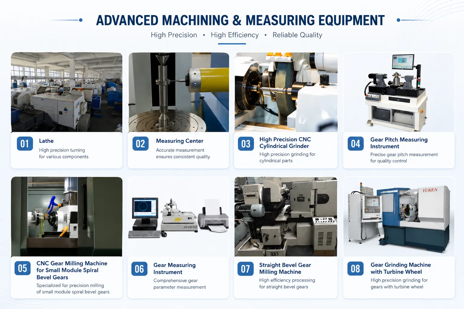
The correct material for a spiral bevel gear depends on three factors: the magnitude of the load (bending and contact stress), the speed (which determines heat generation and required surface finish), and the environment (temperature, corrosion exposure, contamination). The main material categories in use are:
Alloy case-hardening steels (20CrMnTi, 20CrNiMo)
Carburised and quenched to produce a hard case over a tough core. The combination resists both contact fatigue at the flank and bending fatigue at the root. This is the dominant material choice for automotive differentials, industrial gearboxes, and most high-load applications.
Alloy through-hardening steels (42CrMo, 40Cr)
Through-hardened to uniform hardness across the cross-section. Provides good toughness for shock-loaded applications and is easier to repair by re-machining since the hardness does not depend on a case layer. Used in construction equipment, agricultural drives, and general-purpose industrial gearboxes where cost is balanced against load capacity.
Stainless steels (304, 316, 17-4PH)
For food processing, marine, and chemical plant environments where corrosion resistance is required. 316 adds molybdenum for chloride resistance; 17-4PH can be age-hardened to higher surface hardness where load demands it. Load capacity is lower than alloy steel at equivalent tooth size.
Cast iron and non-ferrous alloys
Grey cast iron is used for large, low-speed bevel gears where cost and vibration damping are more important than maximum load capacity. Brass and aluminium alloys are used in lightly loaded instruments, hand tools, and low-torque motion control applications.
Installation Notes and Pair Replacement
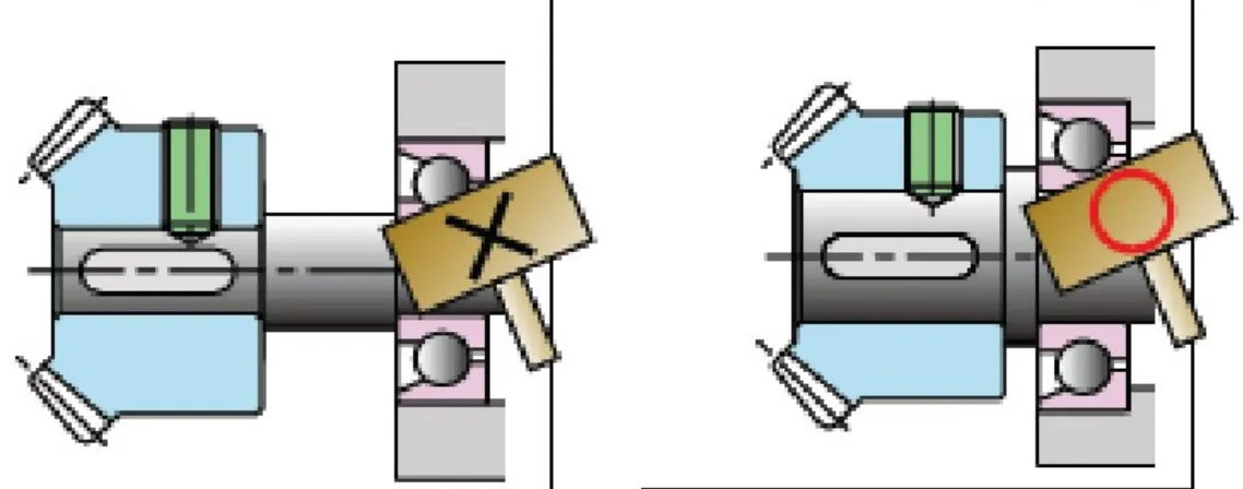
Two installation principles apply to spiral bevel gears that do not apply to spur or helical gears in the same way:
1. Always replace as a matched pair
Ring gear and pinion are manufactured and lapped together. The contact pattern — and therefore the load distribution, noise level, and fatigue life — is optimised for that specific pairing. Installing a new pinion against a worn ring gear, or vice versa, produces a contact pattern that neither member was designed for. In practice this usually results in accelerated wear or early pitting on the new part. When one component reaches the end of its service life, replace the complete set.
2. Hold mounting distance precisely
The mounting distance — the dimension from the gear's mounting face to the pitch cone apex — must be set to the design value during assembly. Korea Ever-Power supplies this dimension with every set. Set it using the reference contact pattern photograph supplied: blue-dye several teeth, rotate the pair by hand under light load, and read the print. A correct no-load print sits near the toe and at mid-tooth height. Shim to correct if the print sits at the heel or toe edge before putting the drive into service.
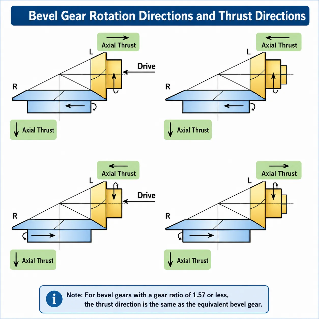
The diagram above shows how the hand of spiral and the direction of rotation together determine the direction of axial thrust on the pinion shaft. In most right-angle drives the pinion shaft bears the larger thrust load. Design the pinion shaft bearing to handle this thrust — typically a paired angular contact bearing or a taper roller bearing set — and size it for the full operating thrust plus an appropriate dynamic safety factor.
Frequently Asked Questions
Why does a spiral bevel gear need to be replaced in pairs?
Ring gear and pinion are lapped together during the final manufacturing stage. Lapping runs the pair against each other with a mild abrasive compound, fine-tuning the contact pattern until it sits correctly on both gears simultaneously. The resulting contact geometry belongs to that specific matched pair — the microscopic surface topography of each tooth is complementary to the other. Fitting a new pinion to a worn ring gear (or the reverse) produces a contact pattern that neither part was produced for, which accelerates wear and often causes noise even on the new component. The cost of replacing the complete set is nearly always lower than the consequential damage from running a mismatched pair.
What is the difference between face-milling and face-hobbing for spiral bevel gears?
Face-milling (single indexing) cuts each tooth slot individually. The cutter mills the full slot depth on one tooth gap, the blank is indexed to the next position, and the process repeats. This produces a tooth with a tapered slot width — the gear is sometimes called a tapering-slot or Gleason-type bevel. Face-hobbing (continuous indexing) rotates both the cutter and the gear blank simultaneously, producing teeth with equal slot width (uniform depth). Face-hobbing is faster for high-volume production and produces a uniform-depth tooth that some designers prefer for its predictable contact behaviour. Korea Ever-Power can produce both types; the choice depends on the customer's existing tooling inventory and the design standard they are working to.
Can spiral bevel gears run at high speed without noise?
Up to a certain pitch-line speed, spiral bevel gears run very quietly relative to straight bevel gears. The limit comes from two sources: transmission error (periodic variation in angular velocity caused by tooth spacing inaccuracy) and dynamic excitation from tooth engagement frequency. Noise at high speed is usually a function of gear accuracy class and surface finish rather than an inherent limit of the spiral bevel design. High-accuracy ground tooth spiral bevel gears with low transmission error are used in high-speed printing and aerospace applications specifically because of their ability to run quietly at elevated speed. The practical upper speed limit depends on the specific design; consult our engineering team with your speed and accuracy requirement.
What lubricant should be used in a spiral bevel gearbox?
For enclosed splash-lubricated spiral bevel drives, an ISO VG 220 or VG 320 gear oil with GL-4 or GL-5 EP additive covers most industrial applications at operating temperatures up to 80°C. Spiral bevel gears do not require the special hypoid-rated lubricant that hypoid gears need, because the sliding velocity between tooth flanks is lower than in a hypoid pair at the same pitch-line speed. At operating temperatures consistently above 80°C, or at pitch-line speeds where churning loss becomes significant with a VG 220 grade, a synthetic PAO of the appropriate viscosity provides better thermal stability and lower traction coefficient. Initial oil fill should be drained after the first 500 operating hours to remove any metal particles from the running-in process.
How do I specify the correct hand of spiral?
Hand of spiral is a convention applied to the pinion (the smaller gear of the pair). A right-hand spiral pinion has teeth that, when viewed from the large end, curve away in the clockwise direction. The ring gear of a right-hand spiral pinion set is a left-hand spiral ring gear — they are always opposite hands. The hand determines thrust direction: a right-hand pinion rotating clockwise (viewed from the large end) generates axial thrust pushing the pinion toward its large end. If the axle bearing layout or housing geometry constrains which direction the thrust can go, specify the hand of spiral accordingly and we will confirm the thrust direction at the quotation stage.
Do you accept drawings in metric (DIN) and imperial (AGMA) formats?
Yes. We accept both metric module (DIN, JIS, GB) and diametral pitch (AGMA, ANSI) drawings. Files can be submitted in PDF, DWG, DXF, or STEP format. Where a drawing is provided in one standard and the customer also needs the gear to meet another standard's accuracy class, include both requirements with the enquiry and our engineering team will confirm the combination is achievable before production begins.
What information do you need to prepare a quotation?
Send us your customer drawing (preferred), or a sample gear plus a description of the application. If neither is available, provide: gear ratio, approximate outer diameter of the ring gear, shaft intersection angle, the torque or power being transmitted, the input speed, the operating environment (temperature, lubrication method), and the required service life. We will prepare a feasibility review and indicative price based on this information, and follow up with a formal quotation once the specification is confirmed. Reach us directly for a faster turnaround on urgent enquiries.
Customer Reviews
"We run a right-angle bevel gearbox on a high-speed offset printing press at a pitch-line speed that eliminates most gear suppliers from consideration. Ever-Power supplied a ground tooth spiral bevel set to the accuracy class we needed. After 18 months in production — running three shifts per day — the contact pattern is unchanged from the reference photograph that came with the shipment."
Song Min-gyu | Maintenance Engineer, Seoul Commercial Print Co. · Q4 2025
"We replaced a worn spiral bevel set on a bucket wheel excavator slewing drive. The previous set had been in service for seven years. Ever-Power reverse-engineered from our worn sample, matched the tooth geometry and material specification, and delivered the replacement set with a contact pattern datasheet. The installation went without adjustment — pattern matched first time."
Han Byeong-chul | Plant Engineer, Gangwon Mining Equipment · Q1 2026
"We source spiral bevel gear sets for our pharmaceutical packaging line gearboxes. Material is 316L stainless for FDA compliance. Ever-Power included a material certificate and hardness test report with every delivery. Three years into the programme, zero quality rejections. The documentation package they provide makes our supplier audit process straightforward."
Yoo Ji-won | Supply Chain Manager, Daejeon Pharma Packaging Systems · Q2 2025
"We design compact right-angle gearboxes for industrial automation. The spiral bevel sets from Ever-Power arrive as confirmed matched pairs with the lapping record and contact photograph. The consistency between batches has been reliable — we have not had to re-qualify a production batch since the programme started two years ago."
Im Tae-jun | Product Engineer, Incheon Drive Systems · Q3 2025
"We switched a food-mixer gearbox from a worm stage to a spiral bevel right-angle drive. Efficiency improvement reduced the motor size from 7.5 kW to 5.5 kW for the same output torque, which paid for the gearbox modification cost within the first year of operation. The 316L stainless set from Ever-Power has been in the wash-down environment for 16 months with no visible corrosion."
Kwon Hyun-soo | Process Equipment Manager, Busan Food Machinery Co. · Q1 2026
Request a Quotation for Spiral Bevel Gears
Send us your drawing, sample gear, or application data. Our engineering team reviews and responds within two working days with a feasibility assessment and price. Matched pairs, material certification, and contact pattern documentation included as standard.
追加情報
| Editor |
|---|
関連商品
-
Helical Bevel Gear – Tangential Tooth, Low Noise Bevel Drive
-
Differential Gears – Open, LSD, Torque Vectoring, Forged PM
-
Metal Bevel Gear – M0.15 to M2.0, 11 Alloys, AGMA 13
-
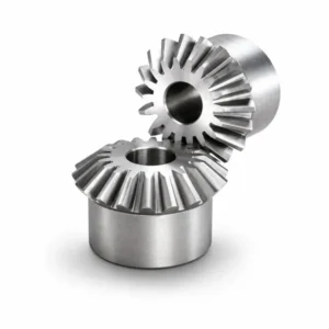
Miter Gears – 1:1 Straight & Spiral, Right-Angle Drive
-
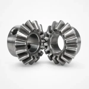
Zero-Degree Spiral Bevel Gear – Zerol, No Axial Thrust
-
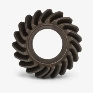
Precision Bevel Gear – M0.15 to M2.2, AGMA 13, 5 HT Routes
-
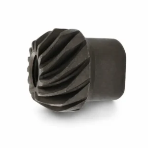
Aircraft Bevel Gear – M0.15 to M2.2, AGMA 13, AS9100
-
Forging Bevel Gears – Hot & Cold Forged, Custom OEM Supply
 Japanese
  English
  Italian
  Korean
  French