
Ground Helical Gear Rack | DIN5-6 Precision, CNC Ground, OEM Supply
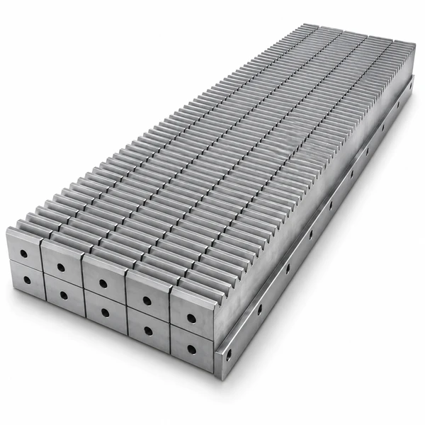
Ever-Power ground helical gear racks are the highest-accuracy variant in the gear rack product family. They combine two performance features that individually give significant benefits — helical tooth geometry and CNC profile grinding — into a single product that delivers the best achievable combination of load capacity, noise level, and positioning accuracy in a linear drive component.
Ground Helical Gear Rack — Product Overview
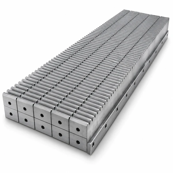
Ever-Power ground helical gear racks are the highest-accuracy variant in the gear rack product family. They combine two performance features that individually give significant benefits — helical tooth geometry and CNC profile grinding — into a single product that delivers the best achievable combination of load capacity, noise level, and positioning accuracy in a linear drive component.
The helical tooth profile gives progressive engagement — teeth enter and leave mesh gradually rather than all at once — which distributes load across multiple contacts simultaneously, reduces transmission error, and dramatically lowers the mesh-frequency noise and vibration that spur racks generate at the same speed and module. Profile grinding after heat treatment removes the distortions introduced by carburizing or induction hardening, achieving pitch deviations below 0.008 mm per 300 mm and tooth-form errors below 0.005 mm. This is the combination required by five-axis machining centres, laser cutting gantries, semiconductor wafer handling systems, and high-speed pick-and-place robots — any application where the encoder alone cannot compensate for mechanical inaccuracy in the drive train.
Specifiche tecniche
| Parameter | Value / Range |
|---|---|
| Tooth Form | Helical (angled); CNC profile ground after heat treatment |
| Modulo | M1, M1.5, M2, M2.5, M3, M4, M5, M6, M8, M10 standard; larger modules per drawing |
| Helix Angle | 19deg31min42sec right-hand standard; left-hand and custom angles per drawing |
| Pressure Angle | 20° standard |
| Grado di precisione | DIN5, DIN6 (CNC profile ground); DIN7 available for pre-ground reference |
| Pitch Deviation | Below 0.008 mm per 300 mm (DIN5); below 0.012 mm per 300 mm (DIN6) |
| Tooth Form Error | Below 0.005 mm (DIN5); below 0.008 mm (DIN6) |
| Surface Finish | Ra 0.4 µm or better on ground tooth flanks |
| Material — Standard | 20CrMnTi case-hardening steel (HRC 58-62 tooth surface); 42CrMo induction hardened (HRC 50-55) |
| Material — Stainless | Stainless steel 304/316 for corrosion-resistant applications |
| Section Length | 1,000 mm standard; custom lengths per drawing; precision half-tooth machined ends |
| Side Ground | Included — side reference faces ground flat for accurate machine base mounting |
| Trattamento superficiale | Phosphating plus oil standard; VCI anti-corrosion packaging for transit protection |
| Documentation | CMM pitch deviation printout, material certificate, heat treatment record, hardness report |
| Standards | DIN 867, JIS B 1702, AGMA 2000, GB/T; ISO 9001:2015 |
Why Ground Helical — vs Milled Helical vs Spur Rack
| Criterion | Ground Helical Rack | Milled Helical Rack | Milled Spur Rack |
|---|---|---|---|
| Pitch deviation /300mm | Below 0.008 mm | 0.020-0.045 mm | 0.020-0.052 mm |
| Positioning accuracy | Below 0.01 mm (closed-loop) | 0.05-0.1 mm | 0.05-0.15 mm |
| Noise level | Very low | Low | Più alto |
| Load capacity (same module) | Highest | High | Standard |
| Surface finish Ra | 0.4 µm or better | 1.6-3.2 µm | 1.6-3.2 µm |
| Tooth hardness achievable | HRC 58-62 (carburized, then ground) | HRC 42-55 | HRC 42-55 |
| Axial pinion thrust | Present — thrust bearing required | Present | None |
| Cost relative | Highest | Medium | Lowest |
| Typical applications | 5-axis CNC, laser cutters, robotics, AS/RS | Servo gantries, packaging | Gates, hoists, conveyors |
Applications of Ground Helical Gear Racks
🔨 Five-Axis CNC Machining Centres
The X and Y travel axes of high-precision machining centres use ground helical racks to achieve positioning repeatability below 0.005 mm over the full machine travel. The low transmission error of a ground rack reduces the vibration that would otherwise appear as surface chatter on the workpiece during finish milling at high feed rates.
🔌 Automation and Robotics
Gantry robots, seventh-axis linear tracks for articulated robots, and SCARA horizontal axes use ground helical racks for their combination of speed and accuracy. At travel speeds above 3 m/s in pick-and-place applications, the smooth transmission characteristic of a ground helical rack keeps positional settling time short and prevents end-effector oscillation after each movement stop.
🚑 Automated Storage and Retrieval (AS/RS)
Stacker crane horizontal axes in high-bay automated warehouses traverse at speeds up to 6 m/s across rack lengths exceeding 100 m. Ground helical racks maintain pitch accuracy across every butt joint, ensuring that the load weight sensor reading is unaffected by positional errors as the crane passes each joint during retrieval.
✈ Aerospace Manufacturing
Large-format aerospace machining jigs, wing assembly fixtures, and fuselage positioning gantries use ground helical racks for their combination of high load capacity and precision positioning. CMM traceability records supplied with each rack section satisfy the aerospace quality documentation requirements applied to production tooling.
📝 Printing Presses
High-speed offset and digital printing presses use ground helical racks in the print head carriage axis. Pitch accuracy below 0.01 mm ensures consistent dot placement across the full print width, maintaining registration between colour separations in multi-pass printing. The quiet mesh reduces paper vibration in the print zone, improving fine-detail reproduction.
🚚 Transportation Manufacturing
Body-in-white transfer lines, door assembly robots, and powertrain assembly tooling in automotive and commercial vehicle plants use ground helical racks on their servo positioning axes. The high duty cycle — often 24 hours per day, 5 to 6 days per week — requires the extended tooth life that ground surface finish and high tooth hardness provide.
Types of Ground Helical Gear Rack
Helix-Tooth Modular Ground
Standard metric module series M1 through M10; helix angle matches standard servo gearhead pinion catalogues. Most interchangeable option — pinion from any major servo brand with matching module and helix angle will mesh correctly.
Hardened Ground Helical Rack
20CrMnTi carburized to HRC 58-62, then tooth flanks CNC ground. Maximum tooth hardness for abrasive environments or high-cycle duty. Used in continuous-operation manufacturing lines and automotive assembly systems.
Stainless Ground Helical Rack
304 or 316 stainless ground to DIN5-6. For corrosion-resistant precision applications in food processing, pharmaceutical, and cleanroom environments where both accuracy and hygiene are mandatory.
Custom Ground Helical Rack
Non-standard module, custom helix angle, special cross-section, or bespoke hole pattern manufactured to your drawing. Full CMM inspection report against the drawing dimensions supplied with the first-article sample.
Maintenance and Usage Guidelines
Lubrication
Use ISO VG 68 way oil via automatic lubrication injector — 0.1 to 0.2 ml per activation cycle. The thin, precisely metered film keeps tooth flanks lubricated without excess oil contaminating guide rails or workpieces. Avoid grease on ground rack drives; grease traps abrasive particles and accelerates flank wear on the precision ground surface.
Alignment and Mounting
Mount the rack with the ground side faces against precision reference surfaces on the machine base. Verify rack-to-machine-axis parallelism using a dial gauge before final bolt torque. Centre distance between rack and pinion must be within 0.01 mm of nominal — use shims at the pinion bearing housing to achieve this.
Inspection and Replacement
Inspect flank condition annually using a gear tooth calliper. Any visible pitting, scoring, or surface breakdown on the ground flank indicates the start of fatigue damage — replace before tooth loss compromises machine accuracy. Replace rack and pinion together to restore the designed contact geometry.
Manufacturing Process
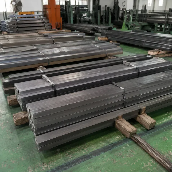
Step 1 — Raw Material
Raw material bar stock verified by spectrochemical analysis before production.
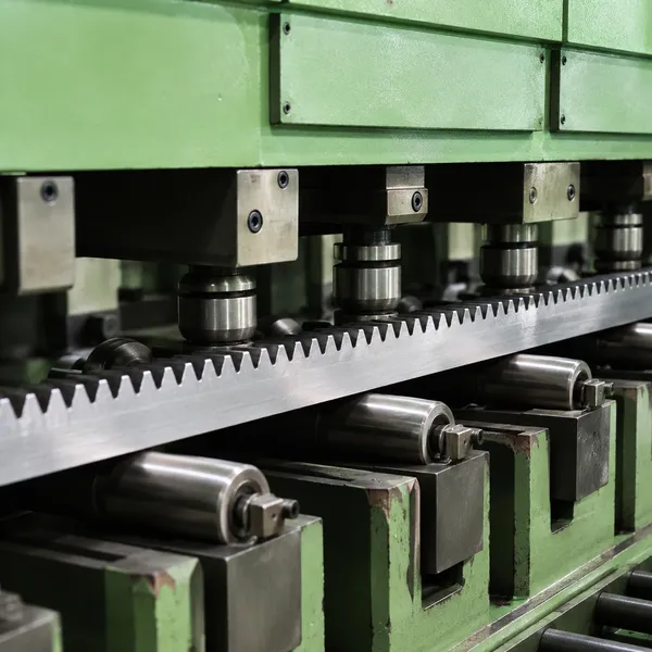
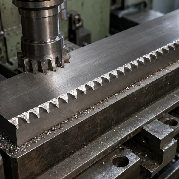
Step 2 — Tooth Cutting
Teeth cut on CNC rack milling or hobbing machine to specified module and pressure angle.
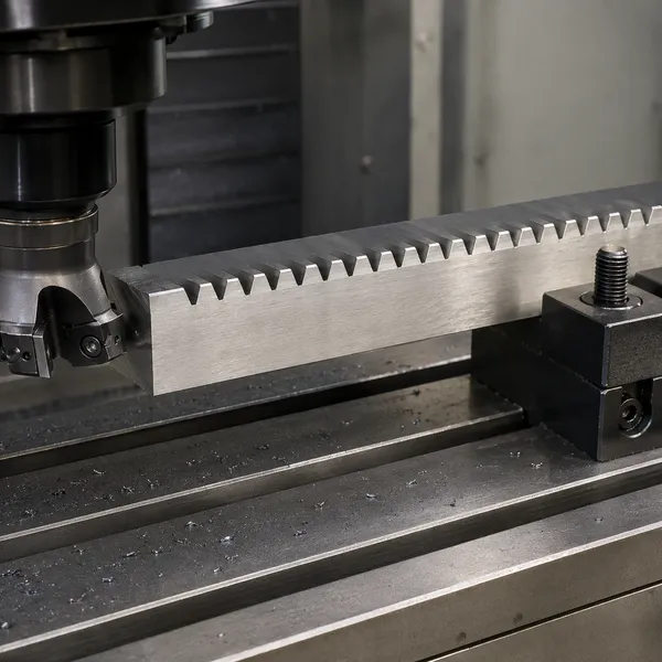
Step 3 — Deburring
Tooth-end burrs removed and edges chamfered to prevent handling damage and sharp corners.
Step 4 — Straightening / HT
Pressure straightening after tooth cutting; induction hardening or carburising where specified.
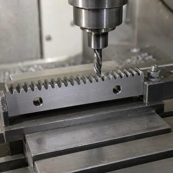
Step 5 — End Machining
End faces and mounting holes machined in CNC machining centre to drawing specification.
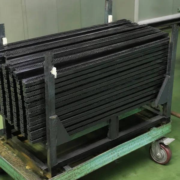
Step 6 — Surface Treatment
Black oxide, zinc plating, phosphating, or hard chrome applied per customer specification.
Key Production Equipment
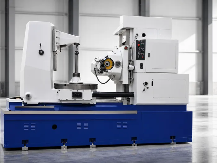
Gear Hobbing Machine
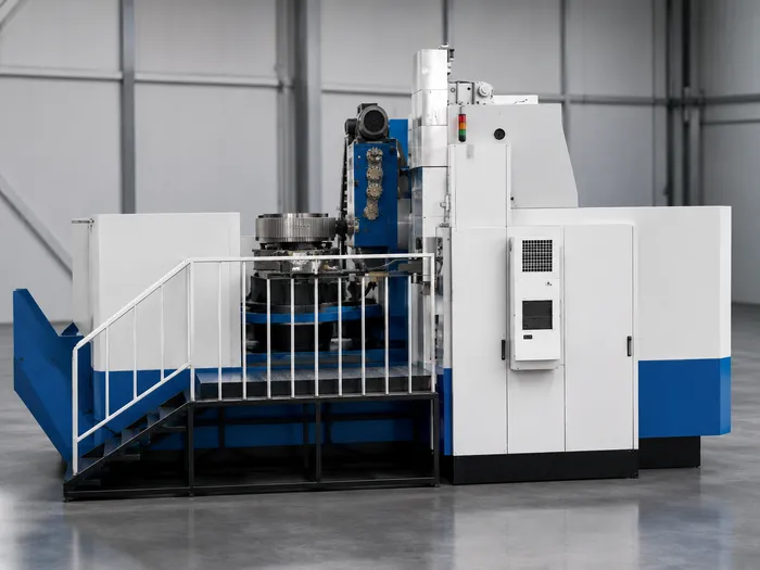
Gear Milling Machine
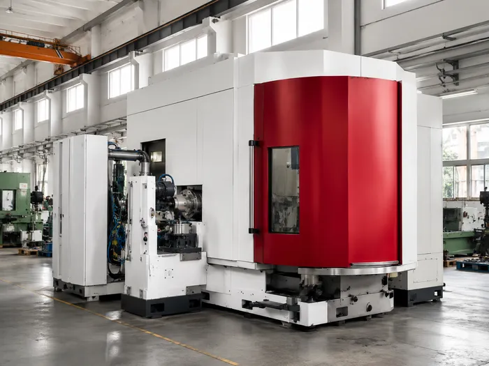
CNC Gear Grinding Machine
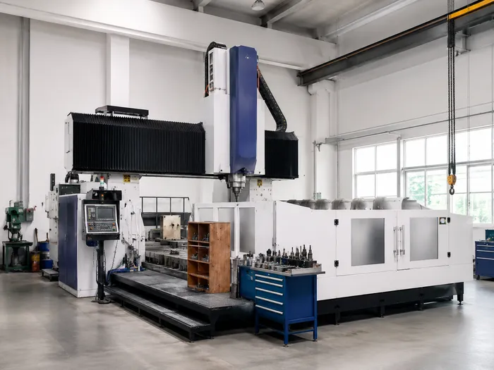
Gantry CNC Machining Centre
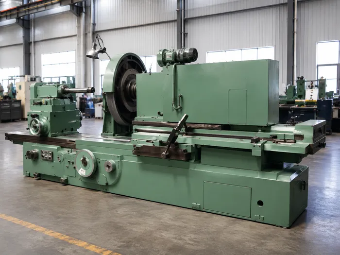
Internal Grinding Machine
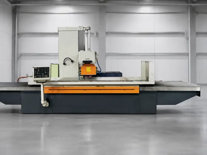
Planer Grinding and Turning
Applications by Industry

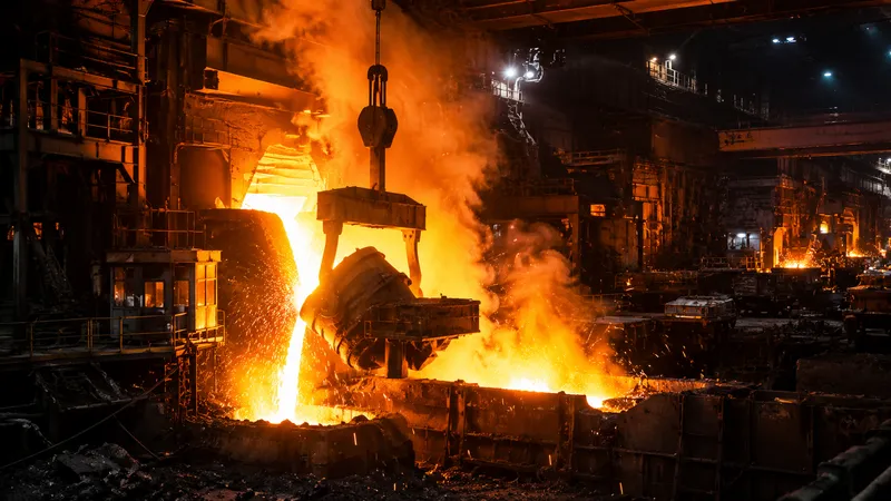
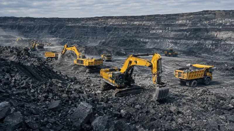





Quality Assurance and Manufacturing
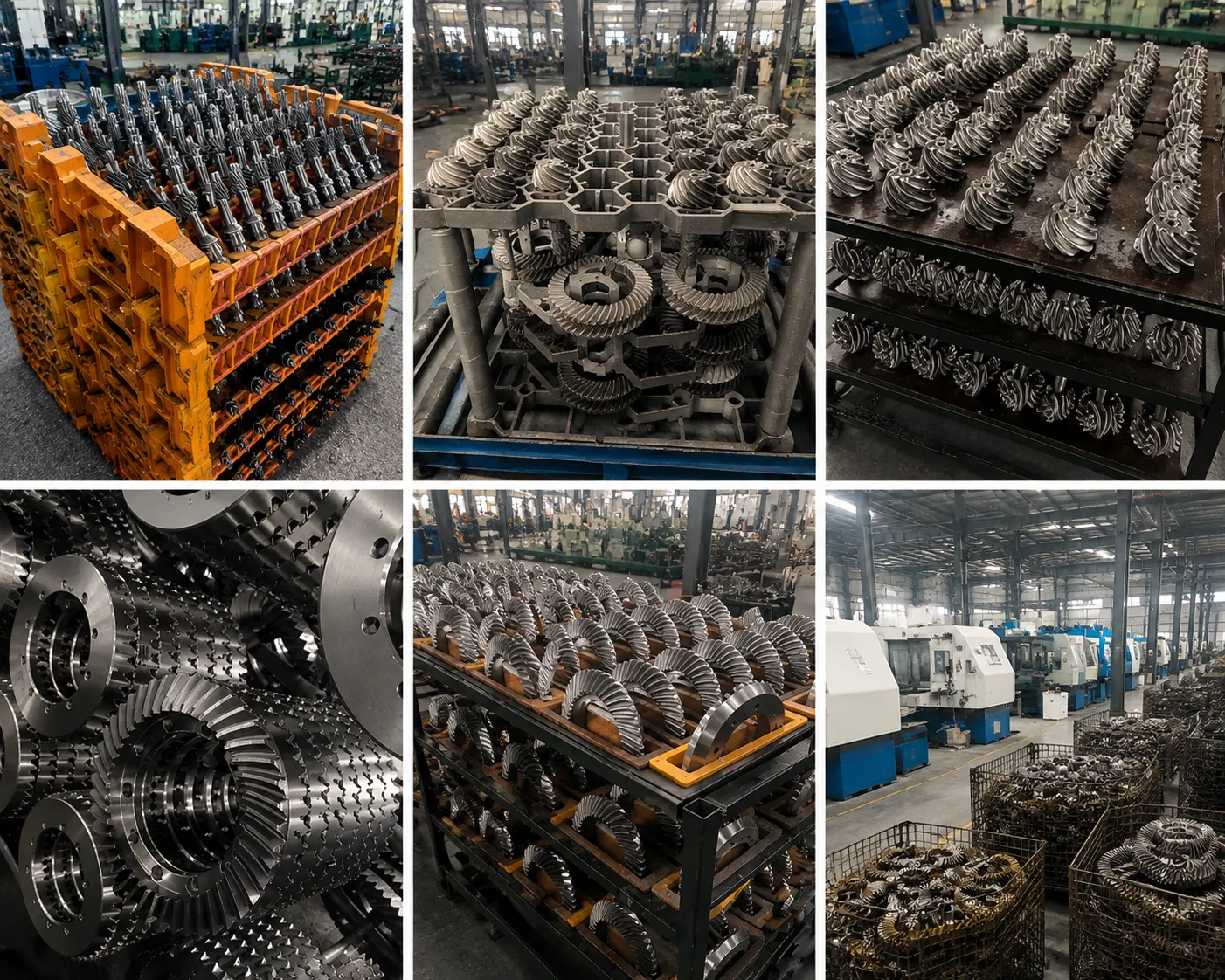
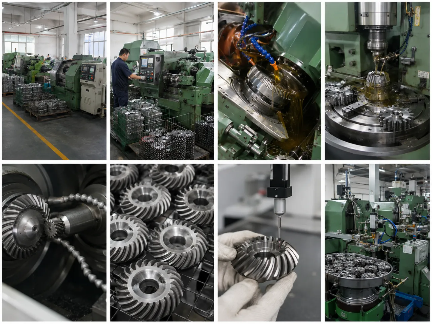
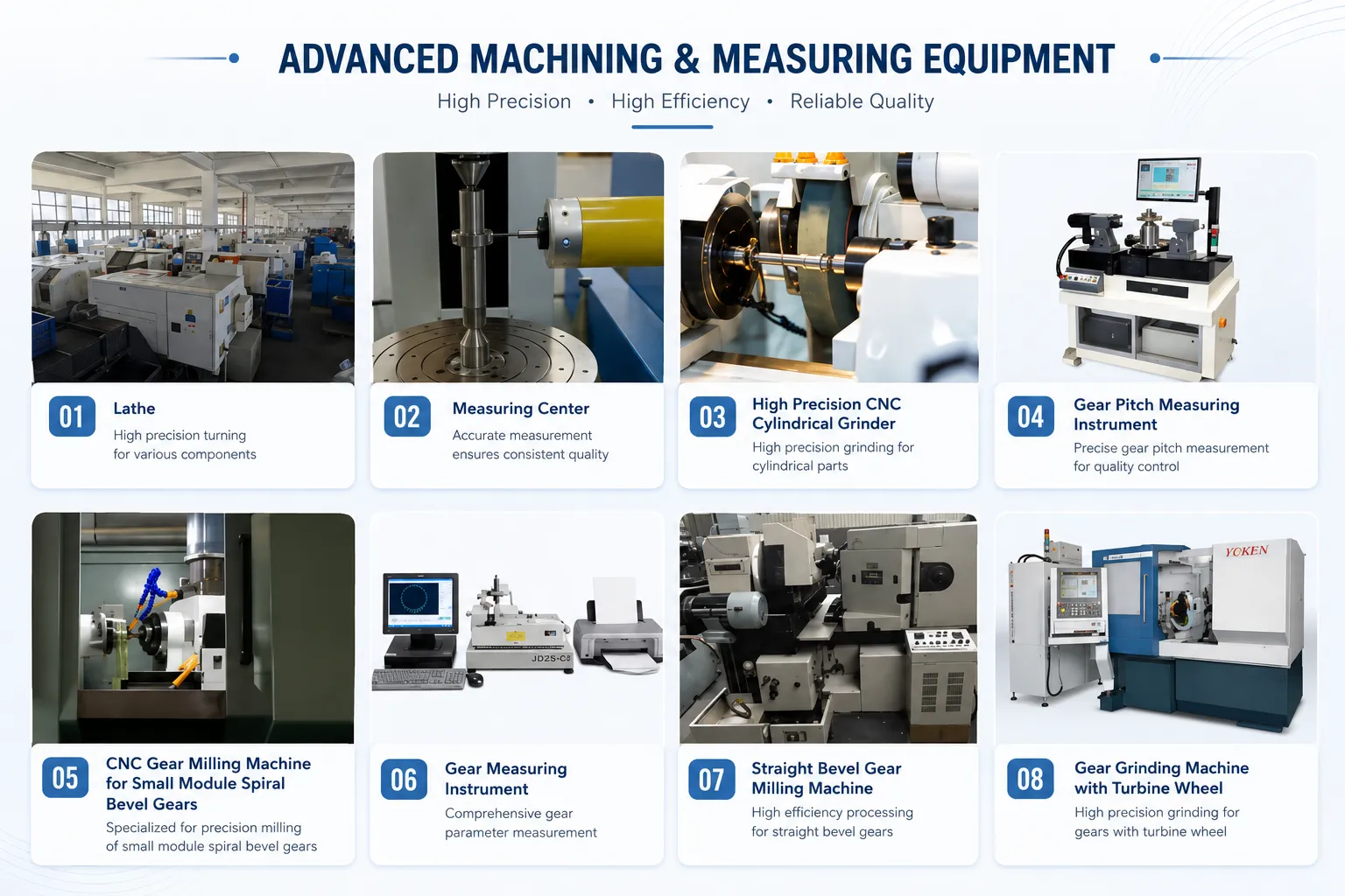
Precision Measurement Equipment
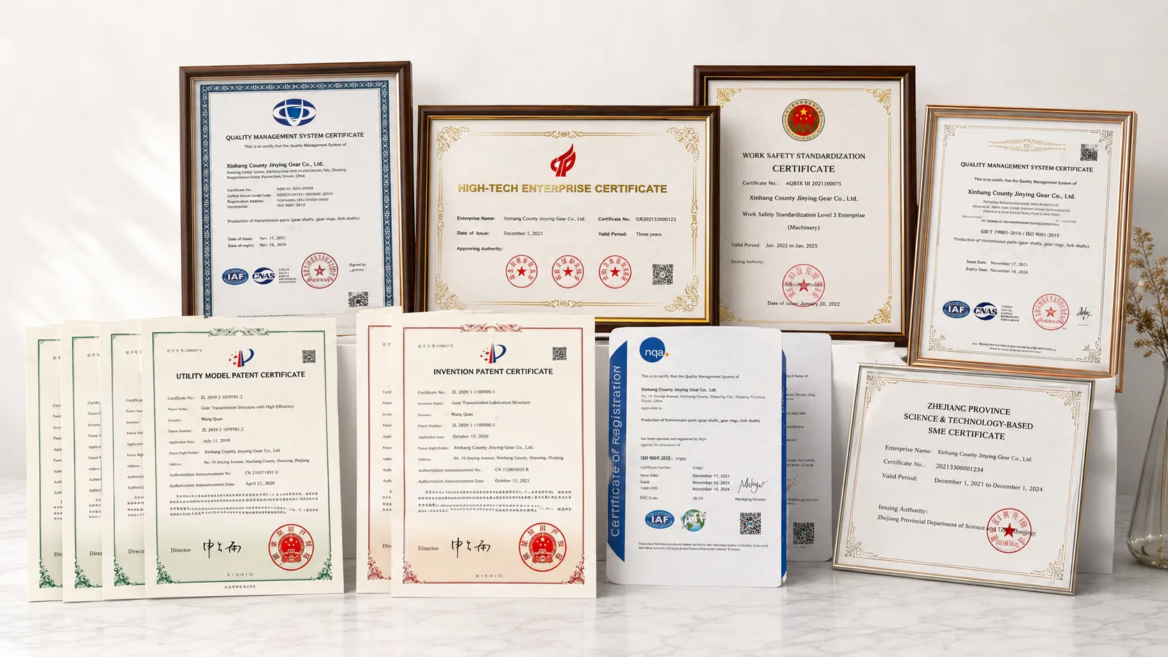
ISO 9001:2015 and Quality Certificates
CNC Gear Grinding Machine
CMM Pitch Deviation Verification
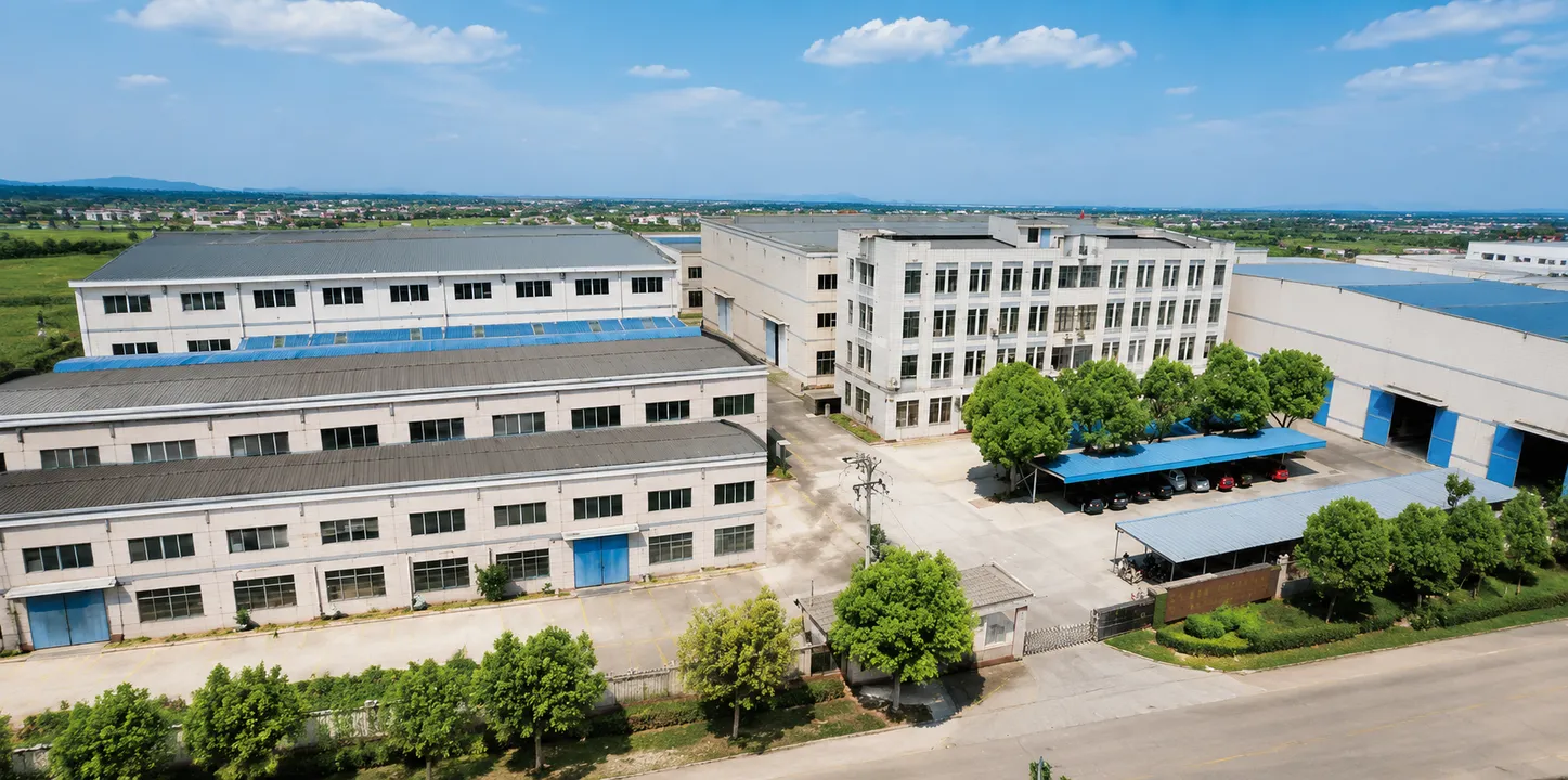
Ever-Power ground helical gear racks are produced on CNC gear grinding machines after carburizing or induction hardening, giving the final tooth geometry entirely independently of the pre-hardening milling operation. ISO 9001:2015 quality management covers every production stage. Every order ships with a CMM pitch deviation printout measured against the DIN5 or DIN6 tolerance band, a material certificate, a heat treatment record showing carburizing time and temperature, and a hardness traverse showing case depth and core hardness. This documentation package meets the quality requirements of aerospace, medical device, and semiconductor equipment OEM programmes.
Browse the full range on the Ever-Power main site: all gear racks, spur gears, helical gears, bevel gears, planetary gear sets, worm gear wheels, ring gears, and plastic gears.
Related Gear Products
Ever-Power manufactures the complete range of industrial gear types alongside gear racks. If your drive system requires matched pinions, reduction gears, or associated gear types, the following product families are available from the same source.
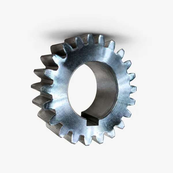
Ingranaggi cilindrici
Pinion gears matching our spur gear rack range; standard modules m0.5 to m20.
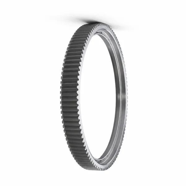
Corone dentate
Large-diameter internal or external ring gears for rotary and slewing drives.
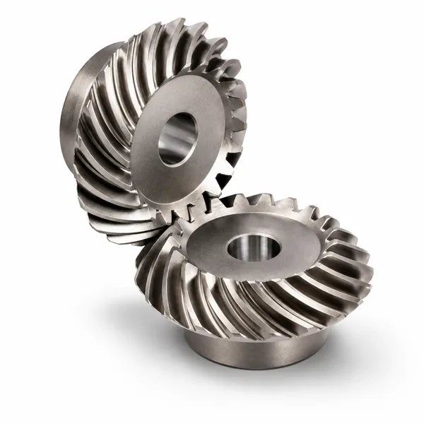
Ingranaggi conici
Straight and spiral bevel gears for right-angle drives and gear motor input stages.
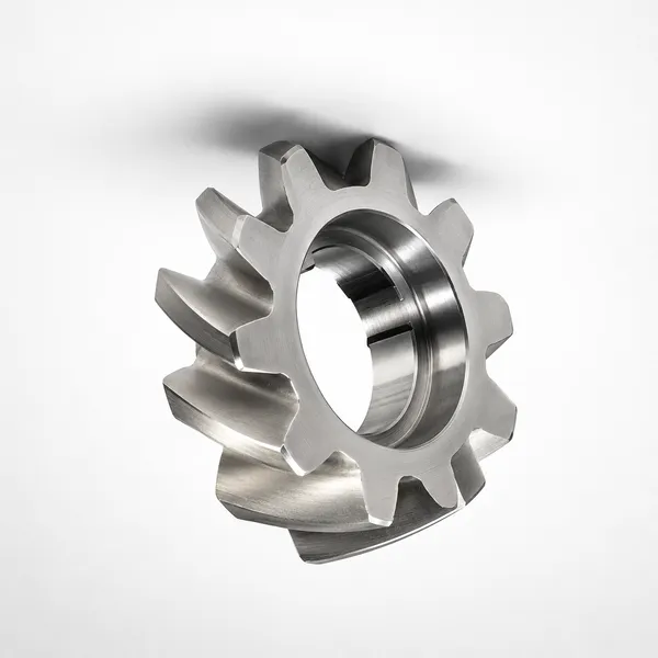
Ingranaggi elicoidali
Helical pinions for high-speed, low-noise rack drives and reduction stages.
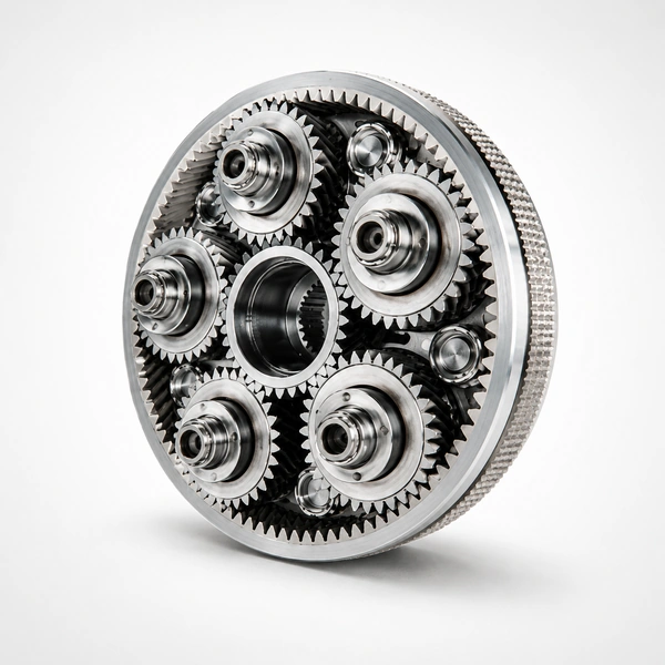
Planetary Gear Sets
Compact in-line reducers paired to servo motors; output shaft connects to the rack pinion.
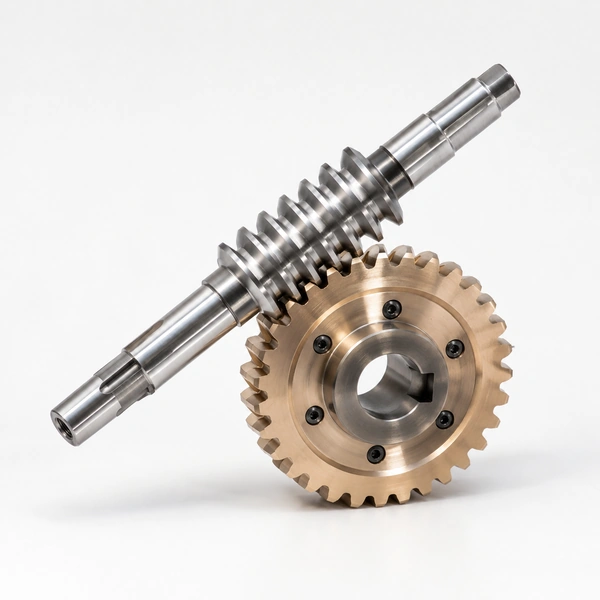
Worm Gear Wheels
Self-locking worm reducers for vertical rack axes holding position under gravity load.
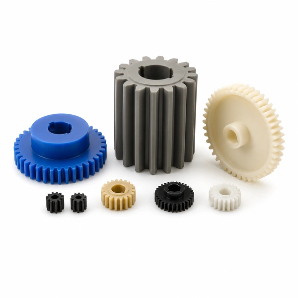
Plastic Gears
Nylon, POM, and polycarbonate pinion gears for light-duty, lubrication-free rack drives.
Domande frequenti
How do I reduce noise and vibration in a ground helical gear rack system?
A ground helical rack already provides the lowest noise level achievable in a rack drive. To further reduce noise: ensure the rack and pinion centre distance is at the nominal value — any excess clearance increases impact noise at mesh; verify pinion and rack helix angles match exactly; maintain a thin, continuous oil film on the tooth flanks at all times; check that all rack section joints are correctly butted with no pitch error at the joint. Residual noise after these checks indicates a worn pinion or bearing noise rather than a rack issue.
What causes excessive backlash in a ground helical gear rack system?
Excessive backlash is caused by: worn gear teeth from insufficient lubrication or overloading; incorrect centre distance — too large a gap between rack pitch circle and pinion pitch circle adds directly to backlash; misalignment between rack and pinion axes causing the mesh to move off the theoretical pitch point; or insufficient preload in a twin-pinion anti-backlash arrangement. Inspect tooth thickness with a gear tooth calliper; check and adjust centre distance; verify alignment; adjust preload per manufacturer instructions.
How can I increase the load capacity of a ground helical gear rack system?
The primary levers are: increase the rack module (larger teeth carry more load per tooth); increase the face width (more tooth contact area per tooth); use a higher-strength material (42CrMo instead of C45, or 20CrMnTi carburized instead of induction-hardened 42CrMo); or use twin-pinion arrangement to share load between two pinions. For a quick assessment, send us your current module, face width, material, and required load, and we will advise the minimum upgrade required to meet your force specification.
What lubricant is correct for ground helical gear rack drives?
For CNC machine and robotics applications with automatic lubrication systems, ISO VG 68 way oil is the standard — it provides adequate film thickness at operating temperature without the viscosity drag of heavier grades, and is compatible with most machine tool slideway materials. Dispense 0.1 to 0.2 ml per lubrication cycle. For operations where no automatic system is fitted, apply ISO VG 100 or VG 150 gear oil by brush or spray to the rack tooth flanks at each scheduled maintenance interval. Avoid EP-additive gear oils on ground racks — the sulphur compounds in EP additives can stain and corrode the precisely ground tooth flanks over time.
Request a Quotation for Ground Helical Gear Racks
Send your module, helix angle, precision grade (DIN5 or DIN6), length, material, and quantity. CMM pitch deviation report included with every order.
Informazioni aggiuntive
| Redattore |
|---|
Prodotti correlati
-
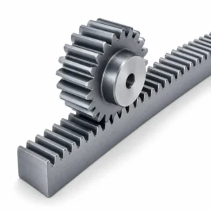
Ground Gear Rack | Precision Ground Spur Rack, DIN5-7, OEM Supply
-
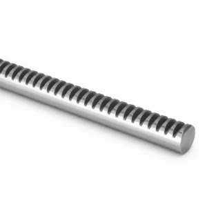
Round Gear Rack | Cylindrical Bar Rack, M1 Steel, Custom OEM Supply
-
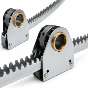
Curved Rack and Pinion Gear | Arc Segment Rack, Stainless Steel, Custom OEM
-
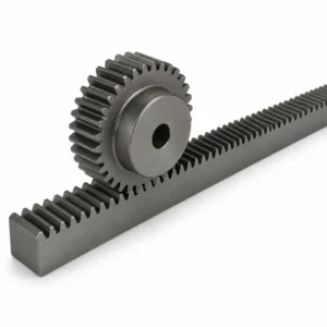
Gear Rack for Construction Elevator | Hoist Rack, M6-M10, OEM Supply
-
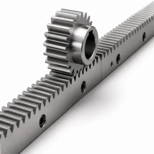
Gear Rack for Rack Actuator | Valve, Gate and Damper Control, OEM Supply
-
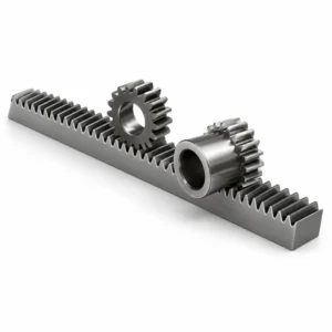
Helical Gear Rack | High-Speed Low-Noise Rack and Pinion, Custom OEM
-
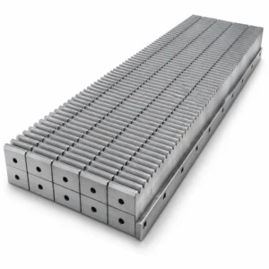
Gear Rack for Machine Tool Industry | CNC, Milling, Grinding, OEM Supply
-
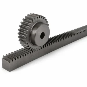
Gear Rack and Pinion | Spur, Helical, Ground and Custom OEM Supply
 Italian
  English
  Korean
  French
  Japanese