GEAR APPLICATION GUIDE · WORM GEAR · W02

Worm Gear Reducers for Conveyors:
Selection, Thermal Rating and Mounting

Worm gear reducers are widely used in conveyor drives where compact right-angle geometry, high single-stage reduction ratio, and low initial cost are priorities over maximum transmission efficiency. This guide covers worm gear reducer selection for belt, slat, and screw conveyor drives — including ratio and efficiency calculation, thermal power rating, service factor, motor sizing, and the efficiency disadvantage that makes spur or helical reducers the better choice above 55 kW.

Bronze Wheel · Alloy Steel Worm · ISO 9001
Ratio 5:1 – 100:1 · 0.12–55 kW Motor
Belt · Slat · Screw · Roller Conveyor

POWER RANGE

0.12 – 55 kW

Practical range for worm gear conveyor drives. Above 55 kW, the efficiency disadvantage vs spur/helical reducer becomes commercially unacceptable for continuous-duty conveyor operation

RATIO RANGE

5:1 – 100:1

Single-stage worm gear conveyor drive. Most common conveyor ratios: 20:1–60:1. Below 10:1 spur gears are more efficient; above 60:1 efficiency drops below 40% — consider two stages

THERMAL RATING

Pth = KsAΔT

Worm reducer thermal power rating limits maximum continuous input power by housing heat dissipation — often lower than the mechanical power rating at high reduction ratios. Always check both

MOUNTING OPTIONS

4 Positions

Worm reducers can be mounted in 4 standard positions (worm above, below, horizontal shaft left or right) — choose position to keep oil level submerging the worm wheel without flooding the shaft seals

Worm Gear Reducers for Conveyor Drives — Selection Logic

The worm gear reducer is the most compact solution for conveyor drives requiring a right-angle input-to-output arrangement (motor shaft horizontal, conveyor head shaft perpendicular) and a high single-stage reduction ratio. In the conveyor drive application, the 90° right-angle geometry of a worm reducer allows the motor to be mounted parallel to the conveyor frame with the output shaft directly engaging the conveyor drive sprocket or head pulley shaft — without the additional angle gearbox or shaft coupling arrangement that a parallel-shaft spur or helical reducer would require when a right-angle drive is needed.

Korea Ever-Power’s worm gear reducers for conveyor applications use phosphor bronze (PB2) centrifugal cast worm wheels and 20CrMnTi or 42CrMo4 hardened alloy steel worms in cast iron or ductile iron housings conforming to DIN 3996 or AGMA 6034 standards. The reducer units are flanged or foot-mounted and available with single output shaft, hollow-bore output shaft for conveyor head pulley direct mounting, or dual-shaft output for conveyors requiring synchronised drives on both ends of the head shaft.

The critical limitation of worm gear conveyor drives is efficiency: the sliding contact at the worm-wheel mesh generates significantly more friction and heat than spur or helical gear contacts. At ratio 40:1, a worm reducer transmits approximately 55–60% of the motor input power to the conveyor head shaft — the remaining 40–45% becomes heat in the gear oil. For conveyors operating at high duty cycle (more than 50% of hours under full load) above 15 kW, this efficiency disadvantage increases energy cost and requires a larger motor than an equivalent spur or helical reducer. Korea Ever-Power recommends spur gear or helical gear reducers for conveyor drives above 55 kW or above 50% duty cycle, and worm reducers for conveyor drives below 15 kW or where the right-angle geometry, self-locking property, or compact footprint justifies the lower efficiency. See also: worm gear reducer specifications for detailed ratio and frame size selection charts.

WORM REDUCER SELECTION CHECKLIST FOR CONVEYOR DRIVES

Step 1 — Required Ratio

i = motor RPM ÷ conveyor head shaft RPM. Head shaft RPM = (belt speed × 60) ÷ (π × head pulley OD). Example: belt 0.8 m/s, pulley ∅250mm: head shaft = (0.8 × 60) ÷ (π × 0.250) = 61 RPM. Motor 1,450 RPM: ratio = 1,450 ÷ 61 = 23.8:1 → select 25:1.

Step 2 — Output Torque

Required output torque = belt pull × head pulley radius. Belt pull (N) = (belt load kg × 9.81) + belt tension. For a 200 kg belt load at ∅250mm head pulley: Tout = (200 × 9.81) × 0.125 = 245 Nm. Confirm reducer rated output torque ≥ 245 Nm at the selected ratio.

Step 3 — Motor Power

Pmotor = (Tout × nout) ÷ (9,550 × η × Ks). At ratio 25:1, efficiency ≈ 75%, Ks = 1.25 (belt conveyor): Pmotor = (245 × 61) ÷ (9,550 × 0.75 × 1.25) = 1.66 kW → select 2.2 kW motor.

Step 4 — Thermal Check

Confirm reducer thermal rating Pth ≥ motor input power at the ambient temperature. At ratio 25:1 and ambient 25°C, a standard cast iron worm reducer Pth = 2.8–3.5 kW for 63–75 frame. 2.2 kW motor < Pth: thermal rating OK. Above Pth, add cooling fan on reducer housing.

Conveyor Type Applications and Worm Reducer Specifications
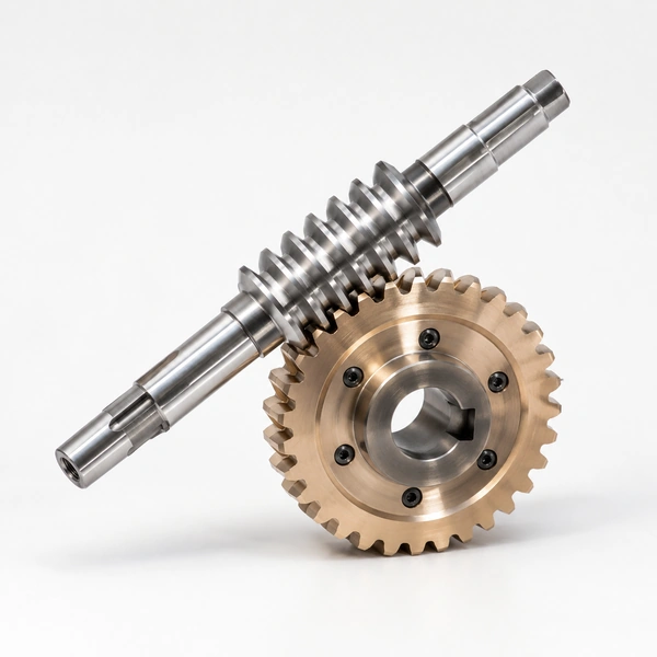
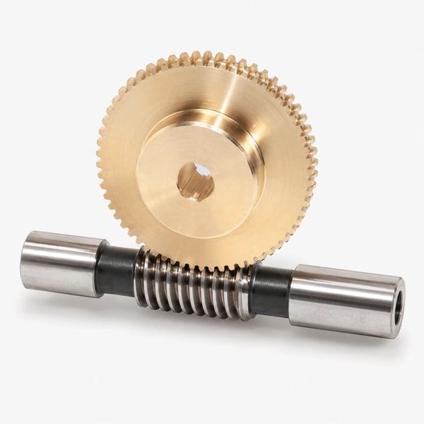
cylindrical worm wheel conveyor reducer Korea Ever-Power
Korea Ever-Power cylindrical worm wheel for enclosed worm gear conveyor reducer — centrifugal cast PB2 phosphor bronze, hobbed and faced to ISO quality class, bore and keyway to H7/JS9 tolerance for conveyor drive shaft mounting. Paired with 20CrMnTi induction-hardened and ground worm shaft. Output torque 150–2,000 Nm depending on frame size, ratio 10:1–60:1. Enclosed splash lubrication with ISO VG 220 worm gear oil; housing drained and filled with worm gear compound before shipment for immediate installation on conveyor drive application.

TYPE 01

BELT CONVEYOR
WORM DRIVE

Worm reducer specification: Ratio 20:1–40:1, frame size IEC 50–75 (for 0.12–7.5 kW motor), B3 or B5 motor mounting, hollow-bore or solid output shaft, ISO VG 220 worm gear oil. Belt conveyor worm gear drives are the most common worm reducer application in light-to-medium industrial conveyor systems — packaging lines, assembly conveyors, e-commerce sortation conveyors, and food production belt drives. The right-angle geometry of the worm reducer allows the motor to lie flat alongside the conveyor frame rather than projecting end-on, which is a significant installation advantage in space-constrained conveyor line layouts. Service factor 1.25 for smooth, continuous belt conveyor drives.

TYPE 02

SLAT / CHAIN
CONVEYOR

Worm reducer specification: Ratio 30:1–60:1, higher service factor 1.5–1.75 for chain chordal impulse loads, hollow-bore output shaft for direct drive sprocket mounting preferred over solid shaft with coupling (eliminates coupling misalignment). Slat conveyors and chain conveyors generate periodic impulse torque at each chain pitch engagement (chordal action) — the service factor increase over a smooth belt conveyor accounts for these peak loads in the worm reducer selection. The worm’s inherent shock-absorbing capacity (the bronze worm wheel deforms slightly under shock, cushioning the impact) is an advantage in chain conveyor applications where spur gear reducers can experience tooth tip fracture under severe chordal impulse.

TYPE 03

SCREW
CONVEYOR

Worm reducer specification: Ratio 10:1–30:1, output shaft directly connected to screw auger shaft by rigid coupling or integral hollow-bore, vertical mounting with worm above oil level for screw conveyor drives where the output shaft is oriented upward or at an angle. Screw conveyor drives have a unique characteristic — the screw can jam on oversized material, producing a sudden torque stall. The worm reducer’s self-locking or near-self-locking property at ratios above 20:1 protects the motor from backdriving during a jam; the worm reducer also absorbs the start-up shock as the jammed screw breaks free after the jam is cleared. Service factor 1.5–2.0 for screw conveyor applications where jam events are expected.

TYPE 04

LIVE ROLLER
CONVEYOR

Worm reducer specification: Ratio 20:1–40:1, very compact frame (IEC 40–50) for 0.12–0.75 kW zone motors in multi-zone live roller conveyor sections, or larger frame for zone-controlled driven roller conveyors. Zone-controlled live roller conveyors in distribution centres use one worm gear motor per zone (typically 2–5 m of rollers), requiring dozens to hundreds of individual small worm reducers per conveyor line. The compact right-angle format and low cost per unit make worm gear motors the dominant choice for live roller zone drives at 0.12–0.37 kW. Above 0.75 kW per zone, drum motors with integral gearmotors may be more cost-effective for large new installations.

Thermal Rating and Efficiency: When to Avoid Worm Reducers

EFFICIENCY vs RATIO

  • Ratio 5:1–10:1: η = 85–92% — competitive with spur gears when right-angle geometry required. Self-locking not achieved at 5:1–10:1 for most material pairs
  • Ratio 15:1–30:1: η = 70–82% — acceptable for conveyor duty below 7.5 kW where space and geometry favour worm reducer
  • Ratio 40:1–60:1: η = 50–65% — motor oversizing of 35–50% required to deliver the rated output torque. Energy cost penalty becomes significant above 1.5 kW in 24/7 conveyor operation
  • Above ratio 60:1: η < 50% — worm reducer thermally limits before reaching mechanical rating. Mandatory thermal check; often requires forced cooling fan or two-stage reducer with spur first stage

WHEN TO USE SPUR/HELICAL INSTEAD

  • Motor power above 15 kW on continuous 24/7 conveyor duty — the energy cost premium of worm reducers outweighs the space and cost saving within 1–2 years of operation
  • Mining and heavy aggregate conveyors above 30 kW — the spur gear open-gear head drive or enclosed spur gearbox is more efficient, more durable at high shock loads, and more maintainable in abrasive mining environments
  • Parallel-shaft conveyor drives where the right-angle geometry is not required — a spur or helical parallel-shaft reducer is always more efficient than a worm reducer at the same ratio
  • Conveyor drives requiring ratios above 100:1 — a two-stage arrangement combining a spur or helical first stage with a worm second stage achieves the ratio with better overall efficiency than a single-stage high-ratio worm reducer

Frequently Asked Questions

Q 01

My worm reducer gets very hot in service on a belt conveyor — what is causing this and how can it be resolved?

Worm gear reducer overheating on a conveyor drive has four possible causes: (1) Input power exceeds thermal rating Pth — the reducer is mechanically adequate but the housing cannot dissipate the friction heat fast enough. Fix: add a cooling fan on the worm shaft, or switch to a helical reducer. (2) Incorrect lubricant — mineral oil used where ISO VG 460 worm gear compound was specified, or oil level too low (exposes worm wheel to air rather than lubricant bath). Fix: drain and refill with correct worm gear oil at correct level. (3) High ambient temperature — the thermal rating Pth is based on 20°C ambient; at 40°C ambient Pth drops by 20–30%. Fix: add ventilation around the reducer or a thermostatically controlled cooling fan. (4) Overloaded or high-ratio application above 60:1 — at ratio 80:1, efficiency is below 40%, generating more than 60% of input power as heat; the reducer is both oversized mechanically and undersized thermally. Fix: two-stage drive with spur pre-reducer or switch to spur/helical reducer. Korea Ever-Power can size the correct reducer and provide the thermal rating calculation for your specific conveyor application.

Q 02

How do I specify the correct lubrication oil grade for a conveyor worm gear reducer?

Worm gear conveyor reducers require gear oil specifically formulated for worm gear contact — do not use standard GL-4 or GL-5 transmission oil. Correct lubricant type is ISO VG 220–460 mineral or synthetic worm gear oil with high film-strength additives for the sliding contact. Viscosity grade selection by input worm shaft speed: worm shaft 1,450 RPM (4-pole motor) in ambient 0–40°C: ISO VG 220–320. Worm shaft 2,900 RPM (2-pole motor) ambient 0–30°C: ISO VG 150–220 (lower viscosity needed as higher speed generates more film). Ambient above 40°C: increase one grade. Ambient below 0°C: switch to synthetic PAO worm gear oil, which maintains pumpability at −30°C. Oil change interval: first change at 500 hours from new (flush out manufacturing debris); thereafter every 4,000–6,000 hours for mineral oil; 8,000–12,000 hours for synthetic PAO in conveyor service. Oil level: worm shaft horizontal — oil level should reach the centre of the worm thread. Worm shaft vertical (worm below) — oil level at the upper bearing. Always check the mounting position code on the reducer nameplate and fill to the correct level plug for that mounting orientation.

Q 03

Can Korea Ever-Power supply replacement worm wheel sets for standard frame worm gear conveyor reducers?

Yes — Korea Ever-Power supplies replacement phosphor bronze worm wheels and matched worm shafts for standard DIN-frame worm reducers (sizes IEC/DIN 030–150) as well as for the most common proprietary worm gear conveyor reducers from SEW-Eurodrive, Rossi, Tramec, TEC, and Chinese standard sizes WP, WPDA, and NMRV series. The replacement worm wheel is the most frequently failing component — the softer bronze wheel wears against the hardened steel worm and eventually loses tooth thickness below serviceable limits. Korea Ever-Power can produce a replacement bronze worm wheel from the worn original (for tooth count, face width, and bore measurement) or from the reducer model number and centre distance. Standard bronze worm wheels in PB2 centrifugal cast material for common frame sizes: 7–15 day delivery from order confirmation. Non-standard or large frame sizes: 15–25 days. Contact Korea Ever-Power with the reducer model, centre distance, and ratio for immediate parts identification and quotation.

Explore Korea Ever-Power Gear Categories

Seven precision gear product lines for industrial, conveyor, automotive and specialist applications worldwide.
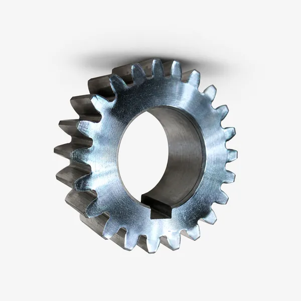
spur gear conveyor

Spur Gears

M1–M20 · C45, 20CrMnTi, 316L

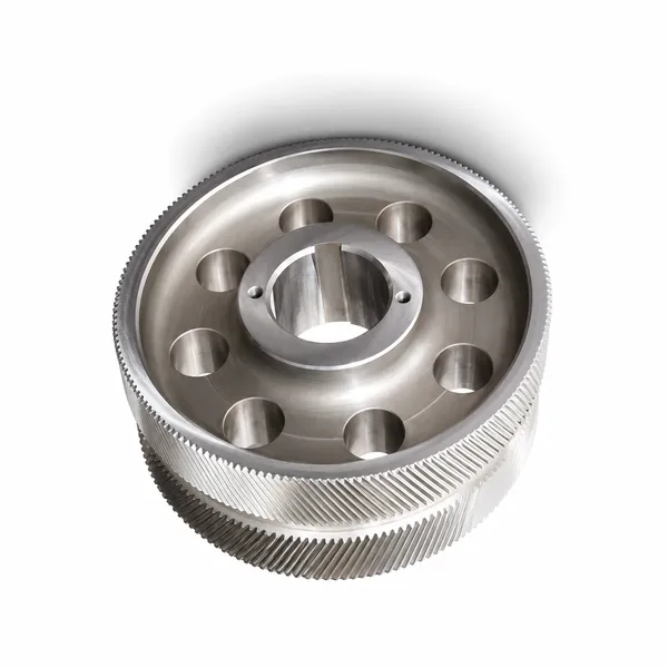
helical gear

Helical Gears

Low noise · high contact ratio · gearbox

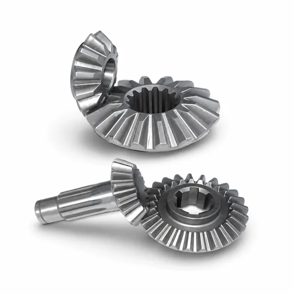
bevel gear

베벨 기어

Right-angle drives · straight & spiral

worm gear reducer

Worm Gears

High ratio · self-locking · valve, hoist

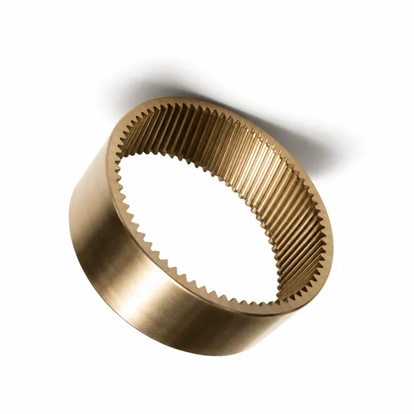
ring gear

Ring Gears

Internal · planetary stage · wind, excavator

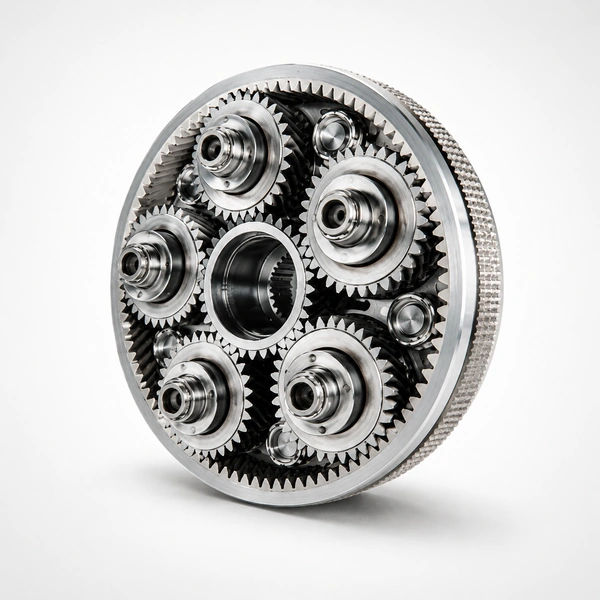
planetary gear

Planetary Gears

Compact · high torque density · servo, EV

plastic gear

Plastic Gears

POM · MC Nylon · UHMWPE · FDA

GET A QUOTATION · KOREA EVER-POWER

Need Worm Gear Reducers for a Conveyor Drive?

Korea Ever-Power supplies complete worm gear reducer units and replacement worm wheel / worm shaft sets for all conveyor applications — 0.12–55 kW, ratio 5:1–100:1, belt, slat, screw and roller conveyor types. DIN-frame and NMRV/WP series compatibility. Replacement bronze worm wheels for SEW, Rossi, and Chinese standard frames in 7–25 days. ISO 9001:2015 documentation included.

Request a Quotation →

편집자: Cxm

VR Tour of Our Factory

TAGs:

기어랙

당사는 기어랙 제조, 공급 및 수출 분야의 선두 기업으로서 기어랙을 비롯한 다양한 제품을 제공합니다.

자세한 사항은 저희에게 문의해 주세요.

우편:[email protected]

기어랙 제조업체, 공급업체, 수출업체

최신 글

ko_KRKorean