
Worm Gear Reducers for Conveyors:
Selection, Thermal Rating and Mounting
Worm gear reducers are widely used in conveyor drives where compact right-angle geometry, high single-stage reduction ratio, and low initial cost are priorities over maximum transmission efficiency. This guide covers worm gear reducer selection for belt, slat, and screw conveyor drives — including ratio and efficiency calculation, thermal power rating, service factor, motor sizing, and the efficiency disadvantage that makes spur or helical reducers the better choice above 55 kW.
Ratio 5:1 – 100:1 · 0.12–55 kW Motor
Belt · Slat · Screw · Roller Conveyor
Worm Gear Reducers for Conveyor Drives — Selection Logic
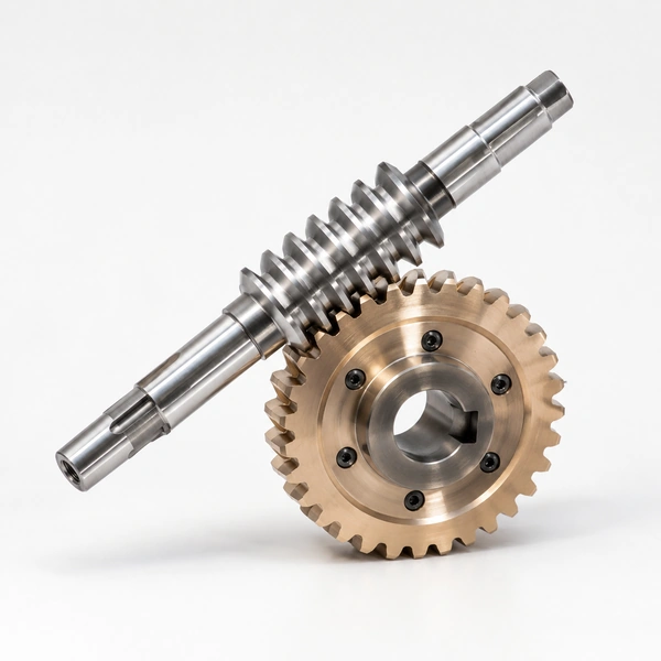
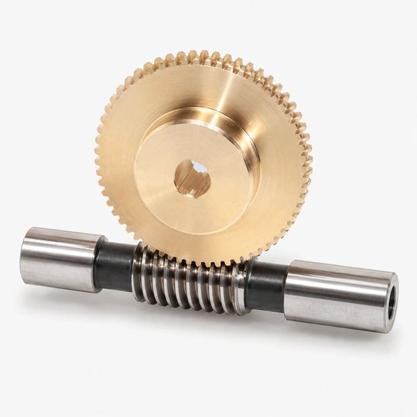
The worm gear reducer is the most compact solution for conveyor drives requiring a right-angle input-to-output arrangement (motor shaft horizontal, conveyor head shaft perpendicular) and a high single-stage reduction ratio. In the conveyor drive application, the 90° right-angle geometry of a worm reducer allows the motor to be mounted parallel to the conveyor frame with the output shaft directly engaging the conveyor drive sprocket or head pulley shaft — without the additional angle gearbox or shaft coupling arrangement that a parallel-shaft spur or helical reducer would require when a right-angle drive is needed.
Korea Ever-Power’s worm gear reducers for conveyor applications use phosphor bronze (PB2) centrifugal cast worm wheels and 20CrMnTi or 42CrMo4 hardened alloy steel worms in cast iron or ductile iron housings conforming to DIN 3996 or AGMA 6034 standards. The reducer units are flanged or foot-mounted and available with single output shaft, hollow-bore output shaft for conveyor head pulley direct mounting, or dual-shaft output for conveyors requiring synchronised drives on both ends of the head shaft.
The critical limitation of worm gear conveyor drives is efficiency: the sliding contact at the worm-wheel mesh generates significantly more friction and heat than spur or helical gear contacts. At ratio 40:1, a worm reducer transmits approximately 55–60% of the motor input power to the conveyor head shaft — the remaining 40–45% becomes heat in the gear oil. For conveyors operating at high duty cycle (more than 50% of hours under full load) above 15 kW, this efficiency disadvantage increases energy cost and requires a larger motor than an equivalent spur or helical reducer. Korea Ever-Power recommends spur gear or helical gear reducers for conveyor drives above 55 kW or above 50% duty cycle, and worm reducers for conveyor drives below 15 kW or where the right-angle geometry, self-locking property, or compact footprint justifies the lower efficiency. See also: worm gear reducer specifications for detailed ratio and frame size selection charts.
WORM REDUCER SELECTION CHECKLIST FOR CONVEYOR DRIVES
Step 1 — Required Ratio
i = motor RPM ÷ conveyor head shaft RPM. Head shaft RPM = (belt speed × 60) ÷ (π × head pulley OD). Example: belt 0.8 m/s, pulley ∅250mm: head shaft = (0.8 × 60) ÷ (π × 0.250) = 61 RPM. Motor 1,450 RPM: ratio = 1,450 ÷ 61 = 23.8:1 → select 25:1.
Step 2 — Output Torque
Required output torque = belt pull × head pulley radius. Belt pull (N) = (belt load kg × 9.81) + belt tension. For a 200 kg belt load at ∅250mm head pulley: Tout = (200 × 9.81) × 0.125 = 245 Nm. Confirm reducer rated output torque ≥ 245 Nm at the selected ratio.
Step 3 — Motor Power
Pmotor = (Tout × nout) ÷ (9,550 × η × Ks). At ratio 25:1, efficiency ≈ 75%, Ks = 1.25 (belt conveyor): Pmotor = (245 × 61) ÷ (9,550 × 0.75 × 1.25) = 1.66 kW → select 2.2 kW motor.
Step 4 — Thermal Check
Confirm reducer thermal rating Pth ≥ motor input power at the ambient temperature. At ratio 25:1 and ambient 25°C, a standard cast iron worm reducer Pth = 2.8–3.5 kW for 63–75 frame. 2.2 kW motor < Pth: thermal rating OK. Above Pth, add cooling fan on reducer housing.
Conveyor Type Applications and Worm Reducer Specifications
Thermal Rating and Efficiency: When to Avoid Worm Reducers
EFFICIENCY vs RATIO
- →Ratio 5:1–10:1: η = 85–92% — competitive with spur gears when right-angle geometry required. Self-locking not achieved at 5:1–10:1 for most material pairs
- →Ratio 15:1–30:1: η = 70–82% — acceptable for conveyor duty below 7.5 kW where space and geometry favour worm reducer
- →Ratio 40:1–60:1: η = 50–65% — motor oversizing of 35–50% required to deliver the rated output torque. Energy cost penalty becomes significant above 1.5 kW in 24/7 conveyor operation
- →Above ratio 60:1: η < 50% — worm reducer thermally limits before reaching mechanical rating. Mandatory thermal check; often requires forced cooling fan or two-stage reducer with spur first stage
WHEN TO USE SPUR/HELICAL INSTEAD
- →Motor power above 15 kW on continuous 24/7 conveyor duty — the energy cost premium of worm reducers outweighs the space and cost saving within 1–2 years of operation
- →Mining and heavy aggregate conveyors above 30 kW — the spur gear open-gear head drive or enclosed spur gearbox is more efficient, more durable at high shock loads, and more maintainable in abrasive mining environments
- →Parallel-shaft conveyor drives where the right-angle geometry is not required — a spur or helical parallel-shaft reducer is always more efficient than a worm reducer at the same ratio
- →Conveyor drives requiring ratios above 100:1 — a two-stage arrangement combining a spur or helical first stage with a worm second stage achieves the ratio with better overall efficiency than a single-stage high-ratio worm reducer
Frequently Asked Questions
Explore Korea Ever-Power Gear Categories
Seven precision gear product lines for industrial, conveyor, automotive and specialist applications worldwide.
Editor: Cxm
 English
  Italian
  Korean
  French
  Japanese