GEAR APPLICATION GUIDE · SPUR GEAR · S01

Spur Gears for Electric Motor Drives:
Speed Reduction and Torque Multiplication

Electric motors deliver peak torque at operating speed but most driven machinery requires lower shaft speed and higher output torque than the motor alone provides. Spur gear reducers bridge this gap — converting motor speed and torque through fixed ratio stages with efficiency above 98% per mesh. This guide covers spur gear ratio selection, stage configuration, efficiency calculation, and motor coupling design for AC and DC electric motor drive systems from 0.12 kW to 315 kW.

C45 · 20CrMnTi · 316L · Nylon
M2 – M12 · Ratio 2:1 – 50:1
IEC B3 / B5 / B14 Motor Mounting

MESH EFFICIENCY

98 – 99.5%

Per spur gear mesh pair at rated load and correct lubrication — highest efficiency of any gear type. Two-stage drive: 96–99%; three-stage: 94–98.5%

RATIO PER STAGE

2:1 – 8:1

Practical single spur gear stage ratio range for enclosed motor gearboxes. Two stages: up to 25:1; three stages: up to 50:1. Higher ratios use planetary or worm stages

TORQUE MULTIPLIED

× ratio × η

Output torque = motor torque × gear ratio × efficiency. A 5 Nm motor through 10:1 spur gear reducer at 98.5% efficiency: 5 × 10 × 0.985 = 49.25 Nm output

MOTOR FRAME RANGE

IEC 56 – 315

Korea Ever-Power spur gear reducers flanged to IEC 56–315 motor frames via B5 or B14 face mount. Foot-mount B3 also available for base-plate motor arrangements

Why Electric Motor Drives Need Spur Gear Reduction

The AC induction motor and the BLDC motor share a fundamental characteristic: their rated torque output is achieved at rated speed, and that speed is almost always higher than the driven machinery requires. A standard 4-pole AC induction motor operates at 1,450–1,480 RPM on 50 Hz supply; a 2-pole motor runs at 2,860–2,900 RPM. The majority of driven applications — conveyor belts at 0.5–2 m/s, mixer agitators at 40–200 RPM, pump impellers at 300–900 RPM — operate far below these speeds and require proportionally higher torques than the motor shaft delivers directly.

Korea Ever-Power’s spur gears for electric motor drives are specified and manufactured for direct coupling to IEC-frame AC motors from 0.12 kW (IEC 56 frame) to 315 kW (IEC 315 frame). The spur gear reducer is the most efficient gear type available for this speed reduction function — per-mesh efficiency of 98–99.5% means minimal heat generation and minimal additional motor loading vs the worm gear alternative that loses 10–50% of motor power to friction at high reduction ratios.

Beyond efficiency, the spur gear drive for electric motor applications offers a second advantage: predictable backlash. For servo motor and stepper motor drives where positioning accuracy is a requirement, the known and measurable backlash of a spur gear reducer — set by the centre distance and tooth thickness at manufacture — allows the control system to compensate for gear lash in the positioning algorithm. Worm gear reducers have less predictable backlash that changes with wear, making spur gear reducers the preferred choice for servo-driven positioning axes at ratios below 20:1.

MOTOR DRIVE REDUCTION — KEY DESIGN EQUATIONS

Required Ratio

i = nmotor ÷ noutput. Example: motor 1,450 RPM, required output 145 RPM: i = 10:1. If a single stage is limited to 8:1, use two stages: i1 = 3.16, i2 = 3.16, total = 10:1 (equal stages minimise gearbox size).

Output Torque

Tout = Tmotor × i × ηn where n = number of stages. Motor 9.55 Nm at 1,450 RPM, 2-stage i = 10, η = 0.985 per stage: Tout = 9.55 × 10 × 0.985² = 92.7 Nm.

Motor Power from Load

Pmotor = (Tload × noutput) ÷ (9,550 × ηn). Load 200 Nm at 80 RPM, 2 spur stages, η2 = 0.97: Pmotor = (200 × 80) ÷ (9,550 × 0.97) = 1.73 kW → select 2.2 kW motor.

Service Factor

Design power = Pmotor × Ks where Ks = 1.0–1.25 for smooth electric motor drives; 1.25–1.5 for motors with frequent starts/stops; 1.5–2.0 for motors with severe shock loading. Spur gear module selected for design power, not nameplate motor power.

Stage Configuration and Ratio Splitting
steel spur gear electric motor drive reducer Korea Ever-Power
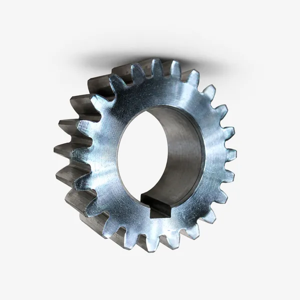
Korea Ever-Power C45 induction-hardened spur gear for AC electric motor reducer application — M5, 24T pinion and 96T wheel (4:1 ratio), face width 60 mm, HRC 50–54 tooth surface. Centre distance 300 mm, pitch line velocity 2.3 m/s at 1,450 RPM motor input. Transmission efficiency 98.7% measured at rated torque. Matched set supplied with individual measurement report confirming module, tooth count, pitch diameter, and DIN quality class.

CONFIG 01

SINGLE STAGE
2:1 – 8:1

Design: One pinion-and-wheel pair. Minimum pinion 17 teeth to avoid undercutting at 20° pressure angle; maximum practical wheel teeth 120–130T before gear OD becomes incompatible with IEC motor frame dimensions. Single-stage ratio ceiling 8:1 (17T pinion / 136T wheel) for standard proportions. Applications: pump drives, fan drives, mixer agitators, and roller table drives where the required output speed is above 200 RPM. Most compact arrangement; highest efficiency (>99% per mesh at correct lubrication).

CONFIG 02

TWO STAGE
8:1 – 25:1

Design: Two spur gear pairs in a common housing on three parallel shafts. Equal ratio split between stages minimises total gearbox size for a given overall ratio: for i = 16:1, use i1 = 4:1 and i2 = 4:1 rather than 8:1 and 2:1 (equal stages produce the smallest gearbox footprint for the given ratio). Two-stage overall efficiency 96–99%. Applications: conveyor head drives, crane hoist drives, mixer drives requiring output speeds of 50–200 RPM from a 1,450 RPM 4-pole motor.

CONFIG 03

THREE STAGE
25:1 – 50:1

Design: Three spur gear pairs in line. Practical for up to 50:1 overall ratio with manageable gearbox dimensions. Above 50:1, a planetary first stage or worm gear stage is usually more compact. Three-stage efficiency 94–98.5%. Applications: slow-speed conveyor drives below 50 RPM output, gate and sluice valve drives, kiln slow-speed turning drives, and lifting winch drives where the low output speed requires extended gear trains from a standard motor speed.

C45 Induction Hardened

The standard for enclosed motor gearbox spur gears in the 2.2–55 kW range. HRC 48–54 tooth flank and root, σH = 900–1,050 MPa. Motor gearbox loads are smooth and continuous — no shock service factor premium needed. Cost-effective for standard IEC motor frame gearboxes at PLV below 5 m/s. Fastest lead time of all steel spur gear options — Korea Ever-Power stocks C45 induction-hardened blanks in M4, M5, M6, M8 for fast turnaround motor gearbox orders.

✓ 2.2–55 kW motor drive standard

20CrMnTi Case Carburized

For electric motor drives above 55 kW, high duty cycle (24/7 operation), or motor drives with frequent starts/stops imposing cyclic loading. Case depth 0.8–1.5 mm, HRC 58–62, σF = 380–430 MPa — provides 2.5–3× the fatigue life of C45 induction hardened at the same module and face width. Ground to DIN 6 for motor gearboxes at PLV above 5 m/s or where gear noise is a specification requirement (indoor industrial, HVAC motor drives).

✓ Above 55 kW, 24/7 or servo motor drives

316L Stainless

For electric motor drives in corrosive environments — marine deck motor drives, chemical plant motor-driven pumps, food processing motor gearboxes. HB 160–200, lower load rating than carbon steel — increase module by one size vs C45 calculation. NSF H1 lubricant compatible. CIP washdown-proof for food processing motor drive applications. Korea Ever-Power supplies 316L spur gear motor drive sets with FDA documentation on request.

✓ Marine, food, chemical motor drive

Nylon / POM Plastic

Plastic spur gears for low-power motor drives to 0.75 kW — servo motor final stage, stepper motor output, BLDC motor drives in office equipment and consumer products. Self-lubricating, low inertia, low noise, zero corrosion. MC Nylon oil-grade preferred for enclosed plastic spur gear motor drives above 0.37 kW for its higher fatigue strength and oil absorption lubrication property.

✓ Low-power servo, stepper, BLDC drives

Motor Coupling, Mounting and Thermal Rating
spur gears European standard motor drive Korea Ever-Power
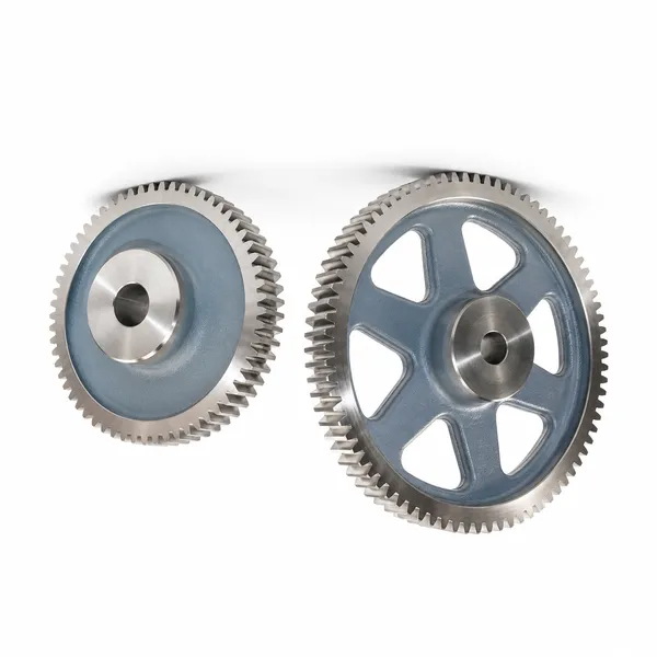
Korea Ever-Power DIN 867 and EN ISO 54 standard spur gears for European motor drive applications — module series M2 to M12, pressure angle 20°, quality DIN 6–8, addendum 1.0×m, dedendum 1.25×m. Interchangeable with all DIN/ISO standard motor gearbox spur gears from European gearbox manufacturers. Available as standard catalogue items in C45 normalised, C45 induction hardened, and 20CrMnTi case carburized for all IEC motor frame gearbox replacement applications.

MOTOR COUPLING

  • B5 face mount (flange): motor flange bolts directly to gearbox input face. Most compact, most rigid. Standard for motor-mounted gearboxes in process plant and conveyor applications
  • B14 face mount (small flange): smaller IEC face dimensions for compact motor gearbox combinations on IEC 56–90 frames. Common in servo motor spur gear reducer packages
  • B3 foot mount + jaw coupling: motor on base plate, spur gearbox separately foot-mounted, connected by flexible jaw coupling. Allows independent alignment and vibration isolation. Used for larger motors above IEC 200 frame where integrated B5 mounting becomes impractical
  • Hollow bore output shaft: spur gear reducer output shaft is hollow, fitting directly over the driven shaft (conveyor head pulley shaft, pump shaft) without a coupling. Eliminates coupling alignment and reduces drive train length

THERMAL RATING

  • Heat generated: Ploss = Pin × (1 − ηn). A 15 kW motor driving a 2-stage 10:1 spur gear reducer at η2 = 0.97: Ploss = 15 × 0.03 = 0.45 kW heat generated in the gearbox housing
  • Oil temperature limit: mineral gear oil maximum 80–90°C bulk oil temperature for ISO VG 220. Above this, synthetic PAO oil to 110°C. Motor gearboxes in high ambient temperatures (>40°C) may require thermal derating or cooling fan
  • Duty cycle: spur gear motor reducers for intermittent duty (S3 30% or S5 cycling) can be rated at higher peak loads than continuous S1 rated gearboxes. Confirm duty class when specifying electric motor drive spur gearboxes for inching, jogging, and positioning applications
  • VFD motor drives: variable frequency drive motors operating below 30 Hz produce reduced cooling flow (motor fan speed proportional to motor speed). Derate spur gear motor drive by 15–25% for continuous VFD operation below 20 Hz, or specify force-ventilated motor

Frequently Asked Questions

Q 01

How do I select the correct spur gear module for my electric motor drive?

Module selection for an electric motor spur gear drive follows five steps: (1) Calculate design power = motor nameplate kW × service factor (1.0–1.25 for smooth motor drives, 1.25–1.5 for frequent starts). (2) Calculate pinion torque = (design power × 9,550) ÷ pinion RPM (RPM = motor RPM for first stage pinion). (3) Select trial module and face width from Lewis bending stress formula or from standard load capacity tables. (4) Verify Hertzian contact stress at the selected module and face width against the material allowable σH. (5) Check pitch line velocity: if PLV > 5 m/s, confirm the selected DIN quality class is achievable (hobbed DIN 7 is adequate below 5 m/s; ground DIN 6 or better required above 5 m/s for enclosed motor gearboxes). Korea Ever-Power can perform this calculation for you — provide motor kW, motor RPM, required output RPM, and duty cycle, and Korea Ever-Power will recommend the correct module, material, and face width for your electric motor spur gear drive.

Q 02

Is a spur gear or helical gear reducer more suitable for my electric motor application?

For most industrial electric motor drive applications operating below 5 m/s pitch line velocity, spur gears are the technically and commercially preferred choice: equal load capacity, simpler housing design (no axial thrust bearings required), and lower manufacturing cost than equivalent helical gear reducers. Choose a helical gear motor reducer when a documented noise specification applies (below 72 dB(A) at 1 m), when pitch line velocity exceeds 6 m/s, or when the application requires compact dimensions that benefit from helical gear higher load density. For all other electric motor drive applications — conveyors, pumps, mixers, hoists, fans — spur gear reducers deliver equivalent performance at lower cost and with simpler maintenance.

Q 03

What lubrication does an enclosed spur gear motor reducer require?

Standard enclosed spur gear motor reducers use ISO VG 220 mineral gear oil at ambient temperatures 0–40°C — the ISO viscosity grade most widely recommended for splash-lubricated enclosed spur gearboxes at pitch line velocities of 1–8 m/s and gear module M4–M10. For ambient temperatures above 40°C or below 0°C, shift one viscosity grade up or down respectively (VG 320 for hot; VG 150 for cold). For motor drives in food processing, pharmaceutical, and potable water applications, use NSF H1 food-grade PAO oil at the same ISO viscosity grade. Synthetic PAO oils are recommended for motor gearboxes running at high ambient temperature (above 40°C) or requiring extended oil change intervals beyond 5,000 hours. Oil change interval: 5,000–8,000 hours for mineral oil; 10,000–15,000 hours for synthetic PAO in enclosed spur gear motor reducers. Check oil level monthly on all enclosed motor gearboxes in production service.

Q 04

Can Korea Ever-Power supply spur gear replacements for existing SEW, Nord, or Bonfiglioli motor gearboxes?

Yes — Korea Ever-Power supplies aftermarket replacement spur gears for all major brand motor gearboxes. The process requires: the gearbox model number (for Korea Ever-Power to reference the OEM specification), or the worn/broken spur gear itself with measured tooth count, OD, bore, face width, and keyway dimensions. Korea Ever-Power can determine the module, pressure angle, and helix (if helical) from these measurements and manufacture a replacement to the same or upgraded material specification. For C45 normalised original gears, Korea Ever-Power upgrades to C45 induction hardened as standard — providing 2–3× the service life of the original at comparable cost. Lead time for standard module M4–M8 single spur gears: 5–12 days. Complete matched pinion-and-wheel sets: 12–20 days. Contact Korea Ever-Power with the gearbox model or gear measurements for a 24-hour quotation.

Explore Korea Ever-Power Gear Categories

Seven precision gear product lines for industrial, automotive, agricultural and specialist applications worldwide.
spur gear

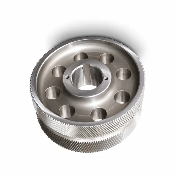
Spur Gears

M1–M20 · C45, 20CrMnTi, 316L, Nylon

helical gear

Helical Gears

Low noise · high contact ratio · gearbox, wind

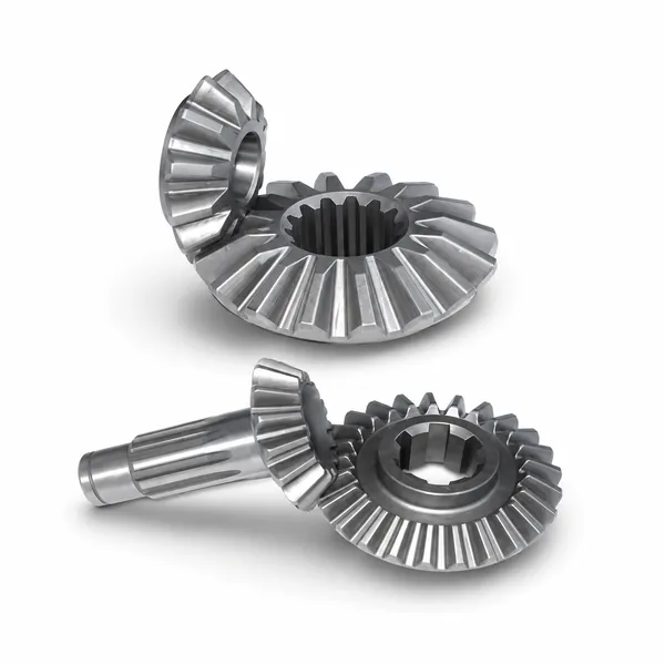
bevel gear

Bevel Gears

Right-angle drives · straight & spiral

worm gear

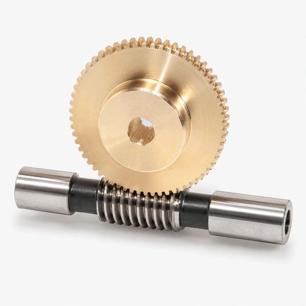
Worm Gears

High ratio · self-locking · valve, hoist

ring gear

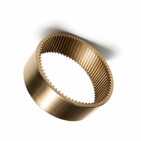
Ring Gears

Internal · planetary stage · wind, excavator

planetary gear

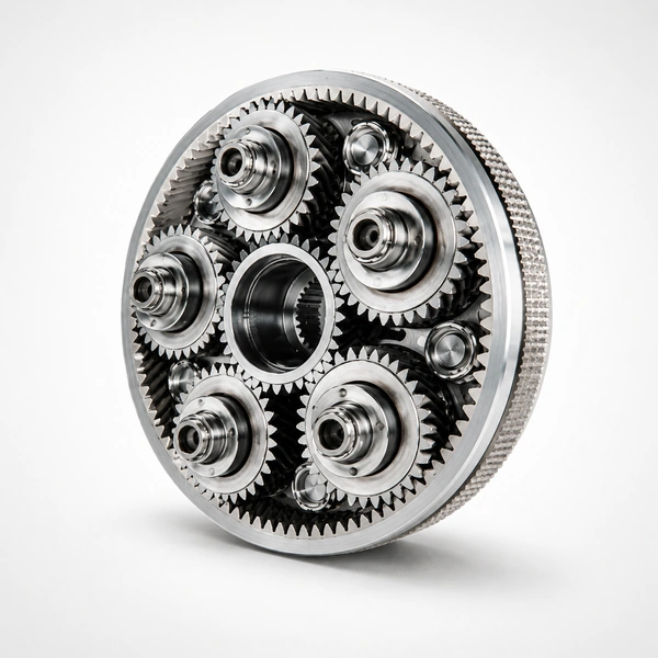
Planetary Gears

Compact · high torque density · servo, EV

plastic gear

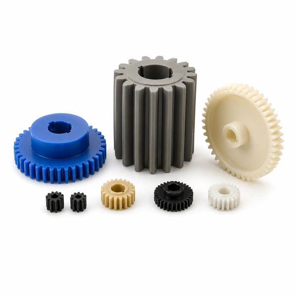
Plastic Gears

POM · MC Nylon · UHMWPE · FDA

GET A QUOTATION · KOREA EVER-POWER

Need Spur Gears for an Electric Motor Drive?

Korea Ever-Power supplies C45, 20CrMnTi, 316L stainless and plastic spur gears for all electric motor drive applications — module M2–M12, single and multi-stage configurations, IEC B3/B5/B14 motor mounting, ratios 2:1 to 50:1. Aftermarket replacements for all major brand motor gearboxes. ISO 9001:2015 quality documentation included.

Request a Quotation →

Editor: Cxm

VR Tour of Our Factory

TAGs:

gear rack

As one of leading gear rack manufacturers, suppliers and exporters of products, We offer gear rack and many other products.

Please contact us for details.

Mail:[email protected]

Manufacturer supplier exporter of gear rack

Recent Posts

en_USEnglish