
Spur Gears for Electric Motor Drives:
Speed Reduction and Torque Multiplication
Electric motors deliver peak torque at operating speed but most driven machinery requires lower shaft speed and higher output torque than the motor alone provides. Spur gear reducers bridge this gap — converting motor speed and torque through fixed ratio stages with efficiency above 98% per mesh. This guide covers spur gear ratio selection, stage configuration, efficiency calculation, and motor coupling design for AC and DC electric motor drive systems from 0.12 kW to 315 kW.
M2 – M12 · Ratio 2:1 – 50:1
IEC B3 / B5 / B14 Motor Mounting
Why Electric Motor Drives Need Spur Gear Reduction
The AC induction motor and the BLDC motor share a fundamental characteristic: their rated torque output is achieved at rated speed, and that speed is almost always higher than the driven machinery requires. A standard 4-pole AC induction motor operates at 1,450–1,480 RPM on 50 Hz supply; a 2-pole motor runs at 2,860–2,900 RPM. The majority of driven applications — conveyor belts at 0.5–2 m/s, mixer agitators at 40–200 RPM, pump impellers at 300–900 RPM — operate far below these speeds and require proportionally higher torques than the motor shaft delivers directly.
Korea Ever-Power’s spur gears for electric motor drives are specified and manufactured for direct coupling to IEC-frame AC motors from 0.12 kW (IEC 56 frame) to 315 kW (IEC 315 frame). The spur gear reducer is the most efficient gear type available for this speed reduction function — per-mesh efficiency of 98–99.5% means minimal heat generation and minimal additional motor loading vs the worm gear alternative that loses 10–50% of motor power to friction at high reduction ratios.
Beyond efficiency, the spur gear drive for electric motor applications offers a second advantage: predictable backlash. For servo motor and stepper motor drives where positioning accuracy is a requirement, the known and measurable backlash of a spur gear reducer — set by the centre distance and tooth thickness at manufacture — allows the control system to compensate for gear lash in the positioning algorithm. Worm gear reducers have less predictable backlash that changes with wear, making spur gear reducers the preferred choice for servo-driven positioning axes at ratios below 20:1.
MOTOR DRIVE REDUCTION — KEY DESIGN EQUATIONS
Required Ratio
i = nmotor ÷ noutput. Example: motor 1,450 RPM, required output 145 RPM: i = 10:1. If a single stage is limited to 8:1, use two stages: i1 = 3.16, i2 = 3.16, total = 10:1 (equal stages minimise gearbox size).
Output Torque
Tout = Tmotor × i × ηn where n = number of stages. Motor 9.55 Nm at 1,450 RPM, 2-stage i = 10, η = 0.985 per stage: Tout = 9.55 × 10 × 0.985² = 92.7 Nm.
Motor Power from Load
Pmotor = (Tload × noutput) ÷ (9,550 × ηn). Load 200 Nm at 80 RPM, 2 spur stages, η2 = 0.97: Pmotor = (200 × 80) ÷ (9,550 × 0.97) = 1.73 kW → select 2.2 kW motor.
Service Factor
Design power = Pmotor × Ks where Ks = 1.0–1.25 for smooth electric motor drives; 1.25–1.5 for motors with frequent starts/stops; 1.5–2.0 for motors with severe shock loading. Spur gear module selected for design power, not nameplate motor power.
Stage Configuration and Ratio Splitting
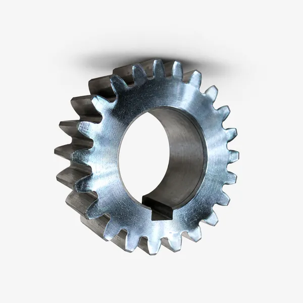
C45 Induction Hardened
The standard for enclosed motor gearbox spur gears in the 2.2–55 kW range. HRC 48–54 tooth flank and root, σH = 900–1,050 MPa. Motor gearbox loads are smooth and continuous — no shock service factor premium needed. Cost-effective for standard IEC motor frame gearboxes at PLV below 5 m/s. Fastest lead time of all steel spur gear options — Korea Ever-Power stocks C45 induction-hardened blanks in M4, M5, M6, M8 for fast turnaround motor gearbox orders.
✓ 2.2–55 kW motor drive standard
20CrMnTi Case Carburized
For electric motor drives above 55 kW, high duty cycle (24/7 operation), or motor drives with frequent starts/stops imposing cyclic loading. Case depth 0.8–1.5 mm, HRC 58–62, σF = 380–430 MPa — provides 2.5–3× the fatigue life of C45 induction hardened at the same module and face width. Ground to DIN 6 for motor gearboxes at PLV above 5 m/s or where gear noise is a specification requirement (indoor industrial, HVAC motor drives).
✓ Above 55 kW, 24/7 or servo motor drives
316L Stainless
For electric motor drives in corrosive environments — marine deck motor drives, chemical plant motor-driven pumps, food processing motor gearboxes. HB 160–200, lower load rating than carbon steel — increase module by one size vs C45 calculation. NSF H1 lubricant compatible. CIP washdown-proof for food processing motor drive applications. Korea Ever-Power supplies 316L spur gear motor drive sets with FDA documentation on request.
✓ Marine, food, chemical motor drive
Nylon / POM Plastic
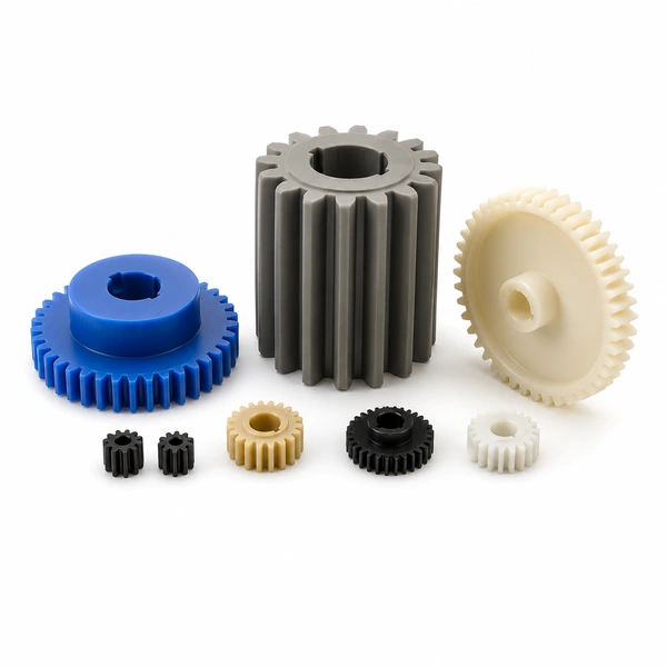
Plastic spur gears for low-power motor drives to 0.75 kW — servo motor final stage, stepper motor output, BLDC motor drives in office equipment and consumer products. Self-lubricating, low inertia, low noise, zero corrosion. MC Nylon oil-grade preferred for enclosed plastic spur gear motor drives above 0.37 kW for its higher fatigue strength and oil absorption lubrication property.
✓ Low-power servo, stepper, BLDC drives
Motor Coupling, Mounting and Thermal Rating
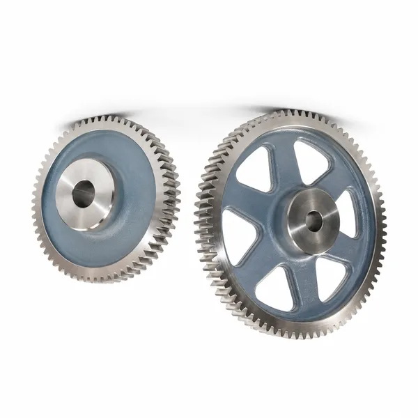
MOTOR COUPLING
- →B5 face mount (flange): motor flange bolts directly to gearbox input face. Most compact, most rigid. Standard for motor-mounted gearboxes in process plant and conveyor applications
- →B14 face mount (small flange): smaller IEC face dimensions for compact motor gearbox combinations on IEC 56–90 frames. Common in servo motor spur gear reducer packages
- →B3 foot mount + jaw coupling: motor on base plate, spur gearbox separately foot-mounted, connected by flexible jaw coupling. Allows independent alignment and vibration isolation. Used for larger motors above IEC 200 frame where integrated B5 mounting becomes impractical
- →Hollow bore output shaft: spur gear reducer output shaft is hollow, fitting directly over the driven shaft (conveyor head pulley shaft, pump shaft) without a coupling. Eliminates coupling alignment and reduces drive train length
THERMAL RATING
- →Heat generated: Ploss = Pin × (1 − ηn). A 15 kW motor driving a 2-stage 10:1 spur gear reducer at η2 = 0.97: Ploss = 15 × 0.03 = 0.45 kW heat generated in the gearbox housing
- →Oil temperature limit: mineral gear oil maximum 80–90°C bulk oil temperature for ISO VG 220. Above this, synthetic PAO oil to 110°C. Motor gearboxes in high ambient temperatures (>40°C) may require thermal derating or cooling fan
- →Duty cycle: spur gear motor reducers for intermittent duty (S3 30% or S5 cycling) can be rated at higher peak loads than continuous S1 rated gearboxes. Confirm duty class when specifying electric motor drive spur gearboxes for inching, jogging, and positioning applications
- →VFD motor drives: variable frequency drive motors operating below 30 Hz produce reduced cooling flow (motor fan speed proportional to motor speed). Derate spur gear motor drive by 15–25% for continuous VFD operation below 20 Hz, or specify force-ventilated motor
Frequently Asked Questions
Explore Korea Ever-Power Gear Categories
Seven precision gear product lines for industrial, automotive, agricultural and specialist applications worldwide.
Éditeur : Cxm
 French
  English
  Italian
  Korean
  Japanese