
GEAR APPLICATION GUIDE · BEVEL GEAR · B01
Bevel Gears for Right-Angle Drives:
Straight vs Spiral Selection Guide
Bevel gears transmit power between intersecting shafts — most commonly at 90° — and are the standard solution for right-angle drive applications in automotive differentials, agricultural PTO drives, industrial angle gearboxes, and marine propulsion. This guide covers straight vs spiral bevel gear selection, shaft angle design, material specification and mounting requirements for all major right-angle drive applications.
Shaft Angle 45° – 135° · AGMA / ISO Standard
20CrMnTi · 18CrNiMo7 · C45 · 316L
Bevel Gear Fundamentals: Transmitting Power at an Angle
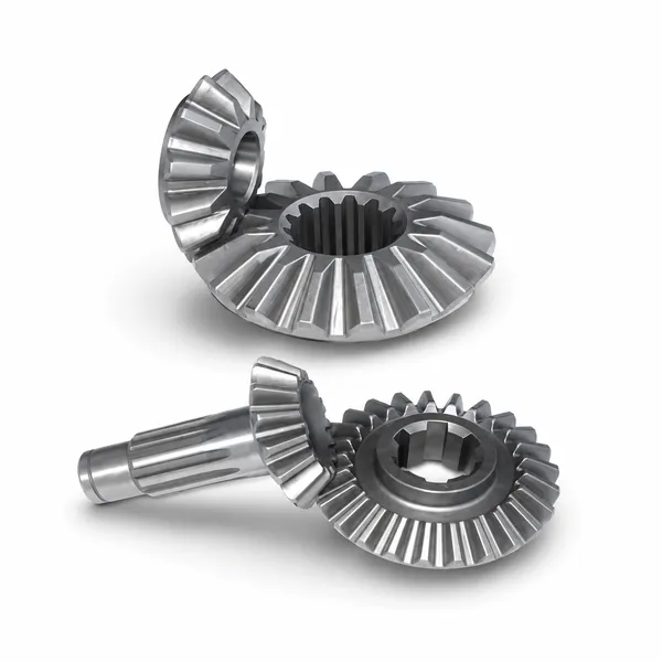
Bevel gears are the engineering solution for power transmission between shafts whose axes intersect — unlike spur, helical, and worm gears which all transmit between parallel or crossing (non-intersecting) shafts. The bevel gear tooth is cut on the surface of a cone, with the tooth form tapering from a larger outer end to a smaller inner end as the cone surface converges toward the apex. Two mating bevel gears share a common apex point where their respective pitch cones touch, and the rotational motion is transferred through the rolling contact of these pitch cones.
The most common bevel gear application is the 90° right-angle drive, where the input and output shafts are perpendicular. Korea Ever-Power’s bevel gears for right-angle drives cover straight bevel gears (M2–M12, shaft angles 45°–135°) and spiral bevel gears (M3–M14, high-speed and high-load applications) in C45, 20CrMnTi, 18CrNiMo7, 316L stainless and engineering plastics. The selection between straight and spiral bevel depends primarily on the operating speed, noise requirement, and transmitted power of the specific right-angle drive application.
Bevel gear drives can accommodate shaft angles other than 90° — angles from 45° to 135° are commercially available, though 90° represents over 90% of all bevel gear right-angle drive applications. At exactly 90° shaft angle with equal tooth counts on both gears (ratio 1:1), the bevel gear pair is called a miter gear pair — both gears are identical, reducing tooling and stocking cost for the common right-angle 1:1 direction change drive.
Straight Bevel Gears
Teeth are straight and radially disposed on the cone surface — full tooth contact occurs simultaneously across the full face width when the tooth enters mesh, similar to spur gears on parallel shafts. Simpler and less expensive to manufacture than spiral bevel; acceptable for low-to-medium speed right-angle drives below 5 m/s pitch cone mean velocity. Generate more noise than spiral bevel at the same speed and load. Standard for agricultural PTO drives, hand tool right-angle drives, slow industrial angle drives, and replacement bevel gear applications.
✓ PLV below 5 m/s · lower cost · simple maintenance
Spiral Bevel Gears
Teeth are curved along a spiral on the cone surface, producing progressive engagement from inner to outer tooth end as the gear rotates — identical in principle to helical gear progressive engagement on parallel shafts. This reduces mesh impact force and noise by 5–8 dB(A) vs straight bevel at equivalent speed and load. Higher face contact ratio allows more compact pitch cone dimensions for the same torque. Standard for automotive differentials, marine propulsion drives, high-speed industrial angle gearboxes, and any right-angle drive above 5 m/s mean pitch cone velocity.
✓ PLV above 5 m/s · quiet · higher load capacity
Hypoid Bevel Gears
Hypoid gears are similar to spiral bevel but with the pinion shaft offset below (or above) the wheel shaft centreline — the axes do not intersect but are offset. This offset allows a larger pinion diameter for the same ratio, increasing pinion strength and bearing span. Hypoid gears are the standard for automotive rear axle final drives where the offset lowers the driveshaft and reduces floor tunnel intrusion. Hypoid gear contact involves significant sliding, requiring extreme-pressure (EP) gear oil that straight and spiral bevel drives do not need.
✓ Automotive rear axle · shaft offset packaging
Material and Heat Treatment for Bevel Gears
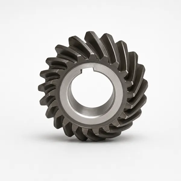
C45 — Straight Bevel, Low-Medium Speed
C45 normalised or induction-hardened for straight bevel gears in agricultural PTO drives, power tool right-angle drives, and slow industrial right-angle drives below 3 m/s pitch cone mean velocity. Normalised: HB 170–210. Induction hardened tooth: HRC 48–54, σH = 900–1,050 MPa. Cost-effective for replacement straight bevel gears and low-volume agricultural OEM bevel gear programmes.
✓ Agricultural PTO, industrial M2–M8
20CrMnTi — Case Carburized Bevel
Standard for industrial straight and spiral bevel gears requiring long service life. Case depth 0.8–1.2 mm, HRC 58–62, σF = 380–430 MPa, σH = 1,400–1,550 MPa. Bevel gear case carburization is more complex than parallel-shaft gear carburization because of the tapered geometry — case depth must be controlled to be uniform at the mean cone radius to maintain the intended tooth strength at all face width positions.
✓ Standard for M4–M12 industrial bevel
18CrNiMo7 — High Power Spiral Bevel
Premium alloy for high-power spiral bevel gears in automotive differentials, marine main reduction drives, and helicopter main rotor gearboxes where maximum fatigue life and shock resistance are required. σF = 430–480 MPa, AKV > 80 J at −20°C. Spiral bevel gears in 18CrNiMo7 are ground on CNC bevel gear grinding machines (Gleason, Klingelnberg) after hardening for the tooth surface accuracy required at high pitch cone velocities.
✓ Automotive, marine, aerospace bevel
316L / POM — Food & Washdown
316L stainless steel straight bevel gears for food processing right-angle drives subject to CIP washdown. POM or MC Nylon plastic bevel gears for light-duty food processing right-angle drives below 0.75 kW — self-lubricating, FDA-listed, zero metal contamination risk. Straight bevel geometry is standard for plastic bevel gears; spiral bevel in plastic is rarely justified by the additional manufacturing complexity.
✓ Food, pharma right-angle drives
Right-Angle Bevel Drive Applications by Industry
Bevel Gear Mounting: Cone Distance, Backlash and Contact Pattern
MOUNTING PARAMETERS
- →Cone distance: mounting distance of each bevel gear from the apex must be held to ±0.05–0.10 mm for M4 and below; ±0.10–0.15 mm for M5–M8 to achieve correct tooth contact pattern
- →Backlash: normal backlash at the pitch cone mean radius: 0.08–0.20 mm for M3–M6; 0.15–0.30 mm for M6–M10. Adjust by moving the gear axially; do not change centre distance
- →Contact pattern: the blue marking contact pattern should fall in the centre one-third to one-half of the tooth face under no-load, shifting toward the outer end (full face under operating load). Never allow toe-heavy (inner end) contact — causes early tooth tip fatigue
- →Shaft perpendicularity: shaft angle error > 0.1° causes significant contact pattern shift and noise increase in bevel drives — check and correct housing bores before assembling new bevel gears
LUBRICATION
- →Straight bevel (low speed): ISO VG 150–220 mineral gear oil or NLGI 2 lithium grease for sealed angle gearboxes in agricultural PTO drives; grease for lifetime-lubricated industrial angle drives
- →Spiral bevel (high speed): ISO VG 100–150 mineral or synthetic gear oil; splash or pressure jet lubrication for PLV above 8 m/s; oil mist for very high speed (above 25 m/s)
- →Hypoid bevel (automotive): GL-5 extreme-pressure (EP) hypoid gear oil mandatory — hypoid sliding contact requires EP additive that standard GL-4 oil does not provide; standard gear oil causes hypoid gear rapid wear
- →Food / washdown: NSF H1 food-grade gear oil for stainless bevel gears in food processing angle drives; POM plastic bevel gears are self-lubricating, no external lubricant required
Frequently Asked Questions
Explore Korea Ever-Power Gear Categories
Seven precision gear product lines for industrial, automotive, agricultural and specialist applications worldwide.
Éditeur : Cxm
 French
  English
  Italian
  Korean
  Japanese