
Spiral Bevel Gears for Automotive Differentials:
Hypoid, Spiral Bevel and Differential Design
The automotive differential gear set — ring-and-pinion plus side gears and spider gears — is among the most critically engineered gear assemblies in any vehicle. This guide covers hypoid vs spiral bevel design for final drives, differential side gear and spider gear specification, gear ratio selection, material and heat treatment requirements, and lubrication for all automotive differential applications from passenger cars to heavy trucks.
SCM420H · 18CrNiMo7 · AGMA 10–12
Passenger Car · SUV · Truck · Performance
Hypoid vs Spiral Bevel — Automotive Differential Design
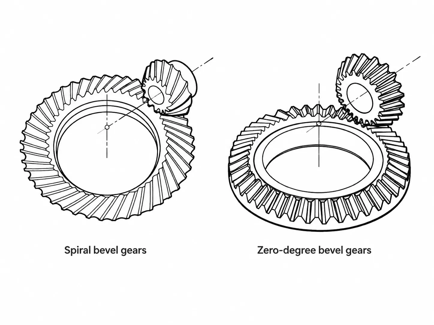
The automotive rear axle final drive uses either a hypoid gear pair or a spiral bevel gear pair to convert driveshaft rotation (from the longitudinal transmission output shaft) to the transverse axle shaft rotation that drives the rear wheels. Both types are bevel gears with spiral teeth — the critical difference is the relationship between the pinion shaft centre line and the ring gear centre: in a true spiral bevel final drive, the pinion axis passes exactly through the ring gear centre (the axes intersect); in a hypoid final drive, the pinion axis is offset below (or above) the ring gear centre by the hypoid offset distance (the axes do not intersect).
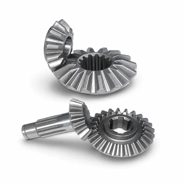
Korea Ever-Power supplies spiral bevel and hypoid ring-and-pinion gear sets for automotive differential applications in SCM420H, 20CrMnTi, and 18CrNiMo7 case-carburizing steel — cut on Gleason and Klingelnberg bevel gear cutting machines and lapped or ground to AGMA 10–12 quality class for the full range of passenger car, SUV, light truck, heavy truck, and motorsport differential applications. Bevel gears for rear axle and transfer case final drives are available as matched ring-and-pinion sets with individual contact pattern test photograph and gear measurement report.
The hypoid offset produces a larger pinion diameter relative to the ring gear for the same ring gear diameter and ratio, compared to a spiral bevel pair — because the larger offset allows a longer, stronger pinion with more tooth contact than the equivalent spiral bevel pinion on an intersecting axis. This strength advantage allowed the hypoid final drive to replace the spiral bevel in almost all passenger car and light truck rear axles from the 1930s onward. The penalty is a large sliding velocity component at the hypoid tooth contact — much higher than in spiral bevel contact — which demands hypoid-specific extreme-pressure (EP) gear lubricant (GL-5 rating) rather than the conventional GL-4 oil used in manual transmissions.
Differential Gear Components: Side Gears and Spider Gears
Ring Gear and Pinion (Final Drive)
The ring gear bolts to the differential carrier and rotates with the carrier at all times. The pinion is integral with or splined to the prop shaft — it drives the ring gear to reduce driveshaft speed and increase axle torque by the final drive ratio. The ring gear is always larger than the pinion; typical passenger car ratio 3.54:1 means the ring gear has 3.54× as many teeth as the pinion. Tooth count ratio selection: use a number of ring teeth and pinion teeth with no common factors (e.g. 43T ring / 11T pinion = 3.909:1) — this “hunting tooth” arrangement ensures every pinion tooth contacts every ring gear tooth in succession, distributing wear uniformly across all teeth rather than concentrating it on specific tooth pairs.
Material: SCM420H or 20CrMnTi for passenger car and light truck; 18CrNiMo7-6 for heavy truck and performance. Case depth 0.6–1.0 mm, HRC 58–63, core HB 330–390.
Differential Side Gears and Spider Gears
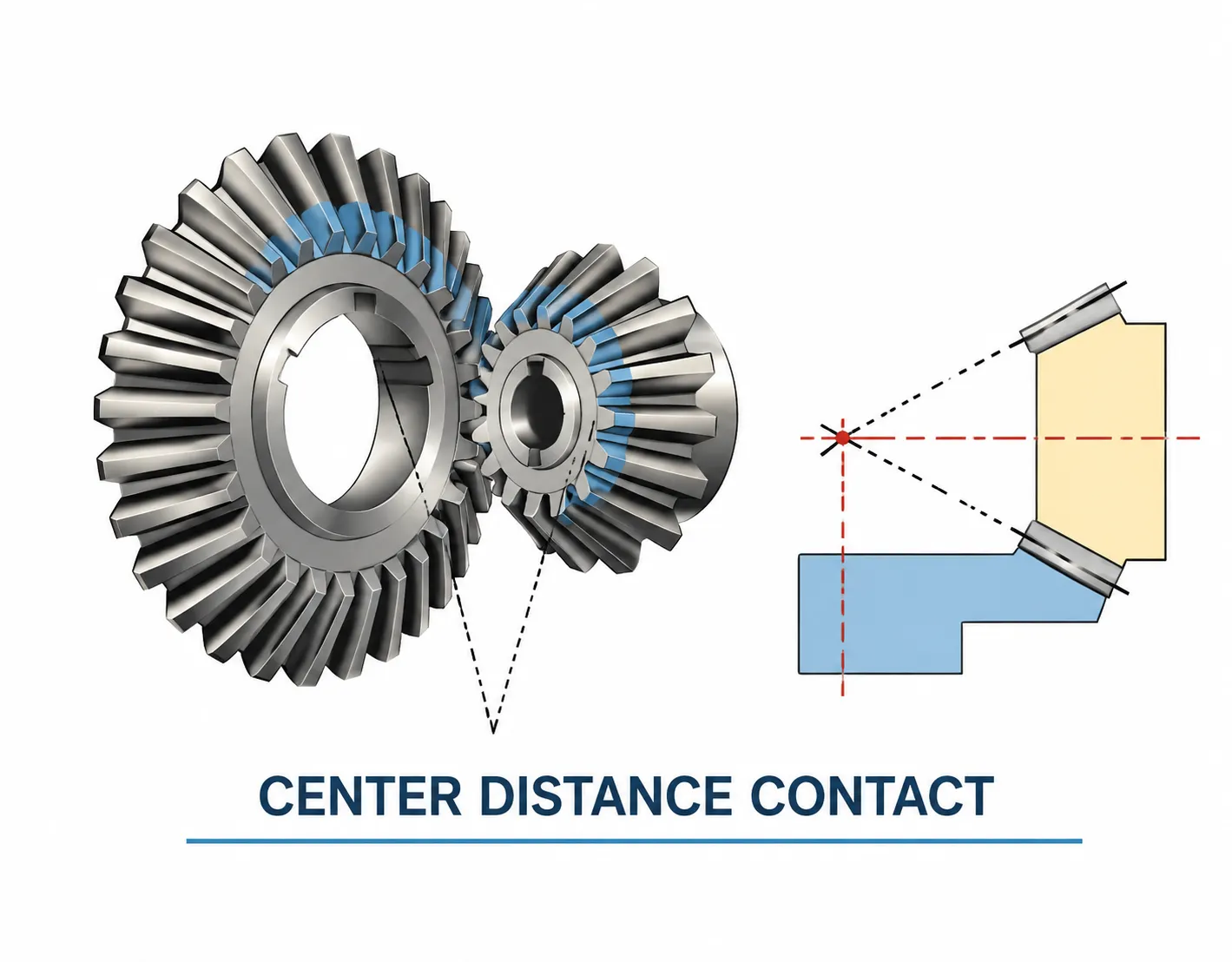
Inside the differential carrier, the side gears (one per axle shaft, splined to receive the axle shaft stub) mesh with the spider gears (also called pinion gears, typically 2 or 4) mounted on pins in the carrier. During straight-line driving, all four gears rotate as a rigid assembly with no relative motion between them. During cornering, the outer wheel must rotate faster than the inner — the spider gears rotate on their pins to allow this speed difference, with each axle shaft turning at a different speed while the sum of the two shaft speeds equals twice the carrier speed. Side and spider gears are straight bevel gears at 90° shaft angle, miter ratio (equal tooth counts on side and spider gears).
Material: SCM420H or 8620 case carburized, M2–M4, straight bevel, 1:1 ratio, case depth 0.5–0.8 mm, HRC 58–62.
Axle Gear Ratio Selection and Its Effect on Performance
The final drive ratio (ring gear tooth count divided by pinion tooth count) is the single tuning parameter that most significantly affects a vehicle’s driving character once the engine and transmission are specified. A numerically higher ratio (e.g. 4.88:1 vs 3.54:1) multiplies the torque at the wheels by a greater factor — giving better acceleration from low speeds and more pulling power when towing — but also increases engine RPM at any given road speed, reducing highway fuel efficiency and limiting top speed. A numerically lower ratio (e.g. 2.73:1) reduces engine RPM at highway speed for better fuel efficiency but reduces low-speed torque multiplication, requiring higher engine torque or a lower first gear ratio to maintain adequate off-the-line acceleration.
Performance vehicle builders and racing teams frequently change the final drive ratio to optimise acceleration vs top speed for a specific circuit or drag strip — a ring-and-pinion ratio change is the most cost-effective way to adjust a vehicle’s power delivery without engine modification. Korea Ever-Power supplies matched ring-and-pinion sets in standard OEM ratios and in performance ratios for the most common American, European, and Japanese rear axle housings (Ford 8.8″, Dana 44, Dana 60, Toyota 8″, Nissan 200mm, BMW 168mm, and others) — contact Korea Ever-Power with the axle housing specification and desired ratio for availability and pricing.
RATIO SELECTION GUIDE
- →Economy / highway commute: 2.73:1–3.08:1 — lower RPM at cruise speed, better fuel efficiency. Requires engine with good torque at low RPM
- →Balanced street / performance: 3.31:1–3.73:1 — compromise between acceleration response and highway RPM. Most OEM performance specification ratios fall here
- →Towing / off-road: 3.73:1–4.10:1 — high torque multiplication for low-speed pulling. Standard on truck and SUV towing packages
- →Drag strip: 4.10:1–4.88:1 — maximum off-the-line torque. Top speed limited; typically used with overdrive transmission
- →Circuit racing: ratio optimised per track — varies from 3.36:1 (high-speed oval) to 5.43:1 (tight circuit with many slow corners requiring strong drive-out acceleration)
DIFFERENTIAL LUBRICATION
- →Hypoid final drive — mandatory GL-5: hypoid contact sliding requires sulphur-phosphorus extreme-pressure (EP) additive in the gear oil. GL-4 oil causes rapid hypoid pinion wear; always use GL-5 (or MT-1 for manual transmission axles with carbon-steel synchros)
- →Viscosity: SAE 75W-90 (full synthetic) standard for passenger car differential; SAE 80W-140 for heavy truck and high-load towing applications; 75W-90 full synthetic for motorsport (lower viscous drag, better high-temperature stability)
- →Limited-slip differentials (LSD): require friction-modifier additive in the gear oil (typically 50–100 ml per axle) — without it, the clutch-pack LSD chatters on low-speed turns. Some LSD designs specify dedicated LSD-rated fluid
- →Change interval: OEM typically 50,000–100,000 km for sealed differentials with synthetic GL-5; 20,000–40,000 km for trailer towing or off-road service; motorsport change after every event
Frequently Asked Questions
Explore Korea Ever-Power Gear Categories
Seven precision gear product lines for automotive, industrial and specialist applications worldwide.
Editor: Cxm
 English
  Italian
  Korean
  French
  Japanese