
Cylindrical Worm Wheel – ISO/DIN, Line Contact, All Materials
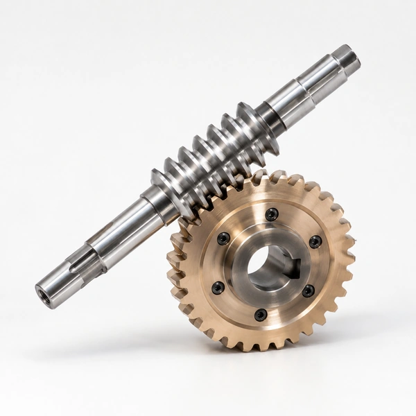
One distinguishes two types of cylindrical worm and worm wheel: a set of worm and helical gear (point contact, light duty) and a set of worm and worm wheel (line contact, industrial standard). The true worm and worm wheel set uses a hob with the same geometry as the worm, producing line contact that gives 3–5× higher load capacity than crossed-helical gears. Materials: brass, C45 carbon steel, stainless steel, bronze, cast iron, aluminium alloy, copper, POM, nylon, PA66, MC, PEER, MSM, Delrin. Heat treatment: quenching and tempering, carburising, high-frequency hardening, carbonitriding. Hardness: 55–60 HRC. Pressure angle: 20°. ISO 9001:2008 certified. AutoCAD and SolidWorks design software. Wooden case or pallet packing.
Product Overview
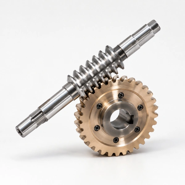
A cylindrical worm wheel is the driven gear in a cylindrical worm and wheel transmission. Two distinct types of cylindrical worm-and-wheel pairs exist in engineering practice: the "worm and helical gear" set, and the "worm and worm wheel" set. Understanding the difference between these two configurations is the foundation for correct worm gear specification, because they differ fundamentally in tooth contact geometry, load capacity, and manufacturing method — and therefore in the applications each type is suited for. Korea Ever-Power supplies both types, precision-manufactured to customer drawing or standard, in materials from brass and bronze through carbon steel, stainless steel, and alloy steel.
Korea Ever-Power's cylindrical worm wheels are designed and manufactured using AutoCAD and SolidWorks, with quality control at every stage from raw material to finished inspection. Equipment failures are resolved by email with photos/videos; damaged parts are replaced free of charge within the warranty period. Customer IPR (design, logo, artwork, tooling) is strictly protected.
The cylindrical worm is named for the shape of its pitch surface — a cylinder, as opposed to the globoid (hourglass) worm whose pitch surface is a toroid. The cylindrical worm is by far the most common worm type in industrial production, and the cylindrical worm wheel mated to it is the standard worm gear for industrial drives, machine tools, and conveyors worldwide.
Technical Specifications
| Cylindrical Worm Wheel — Product Specification | |
|---|---|
| Material | Brass, C45 carbon steel, stainless steel, bronze, cast iron, aluminium alloy, copper, POM, nylon, PA66, MC, PEER, MSM, Delrin |
| Heat Treatment | Quenching & tempering, carburising & quenching, high-frequency hardening, carbonitriding |
| Surface Treatment | Carburising and quenching, tempering, tooth surface high-frequency quench hardening |
| Bore Type | Finished bore, pilot bore, special request |
| Processing Method | Moulding, shaving, hobbing, drilling, tapping, reaming, manual chamfering, grinding |
| Pressure Angle | 20° |
| Hardness | 55–60 HRC |
| Standard | Customer drawings, ISO standard |
| Certificate | ISO 9001:2008 |
| Packaging | Wooden case / container and pallet, or made-to-order |
| Software | AutoCAD, SolidWorks (design and development) |
| QC | Raw material → production → packaging: full-chain quality inspection at each process |
Two Types of Cylindrical Worm and Wheel
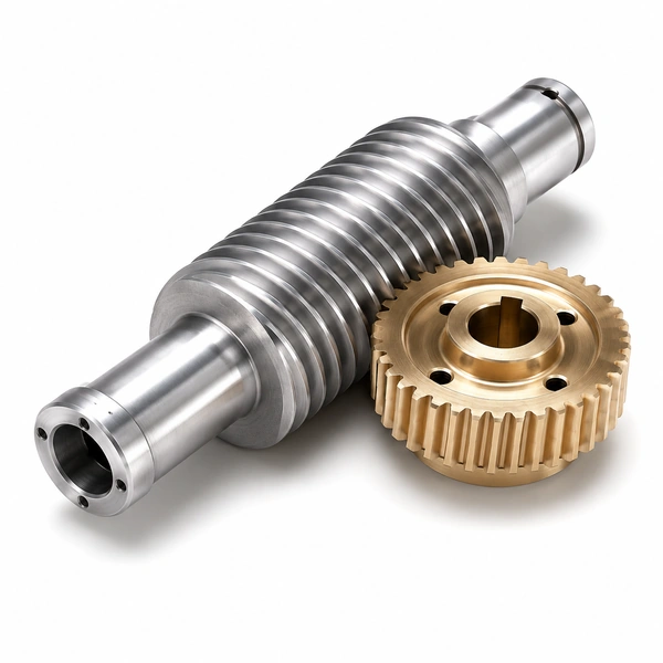
Type 1 — Worm and Helical Gear
The first type is a special case of crossed-helical (skew) gears: the worm acts as a helical pinion with a very small tooth count (1, 2, or 3 teeth) and a correspondingly large helix angle. The mating helical gear is a standard helical spur gear with a matching helix angle. The calculation method is the same as for crossed-helical (skew) gears, and the standard module selection must be from the normalised set of standard modules. Contact geometry: point contact — the tooth flanks of the worm and helical gear touch at a single point. This limits the load-carrying capacity significantly: point-contact transmission is suitable only for light loads and low power transmission.
Suitable for: Light-load right-angle drives in instruments and consumer electronics where simplicity of manufacture (standard helical gear + standard worm) is more important than load capacity.
Type 2 — Worm and Worm Wheel ★
The second type — the true worm and worm wheel — uses a worm wheel whose teeth are hobbed with a worm mill (hob) that has the same basic features as the worm: same module, same pressure angle, same lead angle. The hobbing process removes material from the worm wheel blank in a manner that produces the exact enveloping tooth form — curved in the axial direction — that wraps around the worm thread. Contact geometry: line contact — the worm and worm wheel tooth flanks touch along a line, not a point. This line contact distributes the tooth force over a much larger area, producing 3–5× higher load capacity than the worm-and-helical-gear type at the same module and centre distance.
Standard for: All industrial worm gear drives — conveyor reducers, lifting drives, valve actuators, machine tool feeds, and any application requiring genuine torque transmission capacity.
Cylindrical Worm Wheel Lubrication and Arrangement
Correct lubrication of the cylindrical worm wheel drive depends critically on the physical arrangement of the worm and worm wheel — specifically, whether the worm is below the worm wheel (standard immersion arrangement) or above it (overhead arrangement). The choice of arrangement affects oil flow to the mesh and the selection of the lubrication method:
Standard (Worm Below) — Oil Bath
In the standard worm-below arrangement, the worm thread is partially immersed in the oil bath at the bottom of the gearbox. As the worm rotates, the thread carries oil upward into the worm-wheel mesh by the worm's helical action. Oil level is set so that the bottom of the worm thread is immersed but the worm bearing is not excessively deep in oil (excessive immersion causes churning loss). When the oil immersion depth of the worm bearing has reached the required level but the worm itself is not sufficiently covered, an oil-splashing ring can be installed on the worm shaft to carry additional oil to the mesh and bearings.
Overhead (Worm Above) — Forced or Splash
When the worm peripheral speed exceeds 10 m/s, or when the arrangement requires the worm above the worm wheel (overhead type), the worm wheel is immersed in the oil bath instead. The lower-speed worm wheel stirs the oil gently — low churning loss — and the oil level is set to immerse the bottom of the worm wheel teeth. The overhead arrangement reduces oil churning loss, reduces the likelihood of abrasive particles from the oil pool entering the mesh (particles settle to the bottom, away from the worm-above mesh), and is preferred for high-speed worm drives.
Oil Splashing Ring
A disk-shaped ring fitted to the worm shaft between the worm and the bearing, whose outer edge dips into the oil bath. As the worm shaft rotates, the ring carries oil from the bath upward to the mesh zone and to the bearing, providing lubrication even when the oil level is set lower than would be needed to immerse the worm directly. The oil splashing ring is the standard solution for worm-below arrangements where the worm bearing oil level and worm thread immersion requirements conflict, and is specified as standard on many cylindrical worm gear gearbox designs.
Machining Process for the Worm Thread
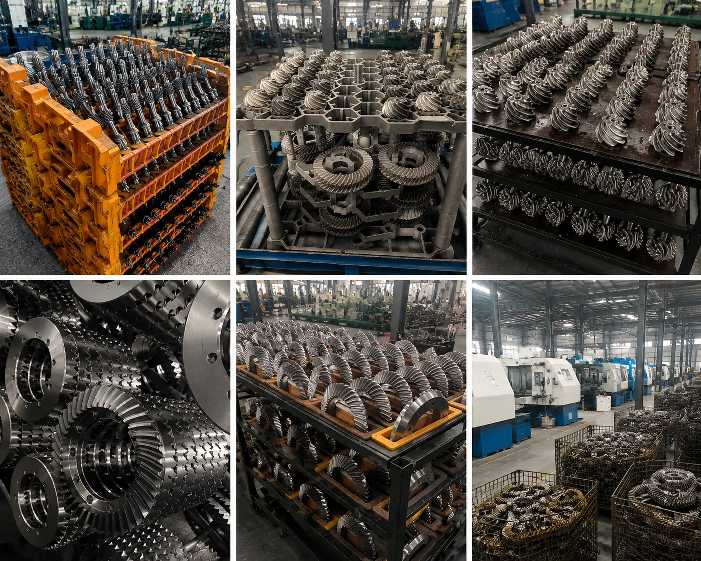
Korea Ever-Power's cylindrical worm thread machining follows: material preparation → normalising → rough turning → quenching and tempering → semi-finish turning outer circle → rough turning spiral surface → finish turning (fine grinding) inner hole and end face → keyway → semi-finish turning spiral surface → semi-finish grinding outer circle → semi-finish grinding spiral surface → grinding centre hole → fine grinding outer ring → fine grinding helical surface → finished product inspection. This multi-stage process sequence, with hardening before final grinding, produces the ground thread surface finish (Ra 0.4–0.8 µm) that maximises worm gear efficiency and minimises worm wheel wear.
Advantages of Korea Ever-Power Cylindrical Worm Wheels
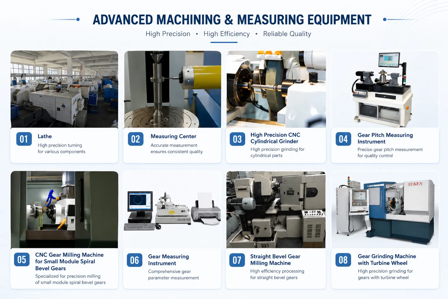
Environmentally Friendly Raw Materials
All raw materials used in Korea Ever-Power cylindrical worm wheel production are environmentally friendly — compliant with RoHS and REACH requirements. Material certifications are supplied with each batch for customers requiring regulatory documentation.
Skilled Production and Packaging
Skilled workers attend to every detail in the production and packaging process — from worm thread grinding accuracy to the correct application of protective oil paper before packing. Packaging defects that cause transit damage are the most common preventable cause of worm wheel tooth damage at incoming inspection; Korea Ever-Power's packaging process is designed to prevent this.
Full-Process Quality Inspection
A dedicated quality control department inspects the cylindrical worm wheel at each process stage — incoming material, rough machining, heat treatment, hobbing, grinding, and final inspection. ISO 9001:2008 certified. Inspection records available on request. Failed parts are removed at the earliest stage of detection to avoid adding value to non-conforming material.
IPR Protection
Customer intellectual property — design drawings, brand logos, artwork, tooling, and custom specifications — is protected under Korea Ever-Power's strict IPR policy. Custom worm wheel designs are not manufactured for third parties. Tooling produced for a customer's design remains exclusive to that customer. NDAs are available for sensitive development projects.
Applications
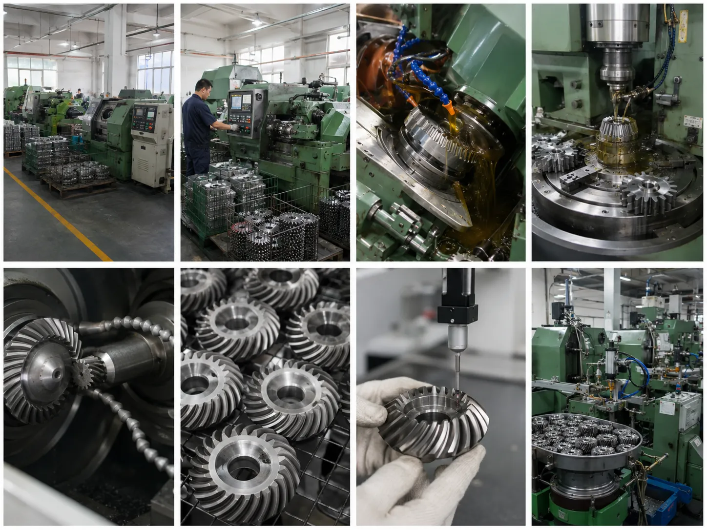
Electric Machinery and Metallurgy
Cylindrical worm wheels in electric motor right-angle drive gearboxes, rolling mill auxiliary drives, and metallurgical handling equipment. High-surface-hardness worm wheels (55–60 HRC, carburised and quenched) for the heavy, shock-loaded duty cycles of metallurgical and heavy industrial drives.
Construction and Road Machinery
Cylindrical worm wheels in concrete mixer drum drives, road roller steering drives, and paving machine auger drives. These are outdoor, dirty environments with wide temperature variation — requiring heat-treated alloy steel worm wheels with corrosion-resistant surface treatment and sealed gearbox arrangements to exclude abrasive particles from the worm mesh.
Water Conservancy and Petroleum
Cylindrical worm wheels in sluice gate actuators, irrigation pump drives, and oil wellhead valve actuator gearboxes. The self-locking property of the worm gear is critical for sluice and valve actuators — the gate or valve must hold position without motor power and without a separate brake, even under the full hydraulic pressure load.
Food and Light Industrial Machinery
Stainless steel or bronze cylindrical worm wheels in food processing conveyor drives, packaging machine right-angle drives, and light industrial right-angle drive units. Stainless steel for washdown food-safe environments; bronze for food-safe oil-bath lubricated drives where the material compatibility with food-grade lubricants is required.
Mining and Transportation Machinery
High-strength alloy steel cylindrical worm wheels in mine hoist auxiliary drives, underground conveyor worm gearboxes, and railway level crossing barrier drives. Mining applications require worm wheels capable of handling shock loads and extended service intervals in environments where maintenance access is difficult.
Chemical, Rubber, and Cement Machinery
Chemical-resistant stainless steel or coated alloy steel cylindrical worm wheels in chemical reactor agitator drives, rubber mixing mill auxiliary drives, and cement plant kiln auxiliary drives. These applications combine high duty cycle, elevated ambient temperature, and chemical or abrasive environment — requiring the most robust worm wheel material selection and surface treatment to achieve acceptable service life.
Frequently Asked Questions
How do I resolve equipment failure during use?
Email Korea Ever-Power the problem with photos or videos — this allows the engineering team to identify the root cause (tooth wear pattern, fracture mode, lubrication condition, or misalignment indication) and provide the correct solution. For damaged worm wheels within the warranty period, Korea Ever-Power will send replacement parts free of charge. Prompt notification with evidence photographs maximises the speed of resolution.
What software does Korea Ever-Power use for cylindrical worm wheel design?
Korea Ever-Power uses AutoCAD and SolidWorks — the industry-standard design and development software — for all cylindrical worm wheel design work. 3D models in SolidWorks allow interference checking, contact pattern simulation, and virtual assembly verification before production begins. Customer drawings in DXF, DWG, STEP, or IGES format are all accepted.
What is the difference between point contact and line contact worm wheel sets, and which should I choose?
The worm-and-helical-gear set (point contact) is simpler and less expensive to manufacture — the mating gear is a standard helical gear — but has much lower load capacity. It is suitable only for light-duty, low-power applications. The true worm-and-worm-wheel set (line contact) has the worm wheel specifically hobbed with a worm-form hob to produce the enveloping tooth profile — this is the standard for all genuine power transmission applications. For any application involving real torque transmission, specify the worm-and-worm-wheel type. Contact Korea Ever-Power with the power, ratio, and centre distance to confirm the correct specification.
Customer Reviews
"We manufacture industrial conveyor right-angle drive gearboxes and source bronze cylindrical worm wheels from Korea Ever-Power. The hobbed tooth profile produces confirmed line contact at our incoming contact-pattern test — the blue marking pattern covers 75% of face width, symmetrically placed. Oil-splashing ring version supplied for our worm-below arrangement; lubrication to the worm bearing confirmed adequate at rated speed. 22 months continuous operation without tooth failure."
Kim Min-seok | Industrial Gearbox Production Engineer, Incheon Drive Systems Co. · Q2 2026
"We build sluice gate actuators for irrigation projects. Specified alloy steel cylindrical worm wheels (carburised, HRC 58, ground thread) from Korea Ever-Power. Self-locking under full hydraulic gate load confirmed at our test bench — zero back-drive rotation recorded. ISO 9001 certificate and material certifications supplied for our government procurement documentation. Delivery: 24 business days bulk."
Lee Jeong-won | Water Control Actuator Engineer, Gyeonggi Water Systems Co. · Q1 2026
Related Products
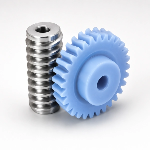
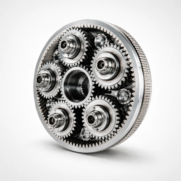
Request a Quotation for Cylindrical Worm Wheels
Bronze, alloy steel, stainless steel, brass — all materials. ISO/DIN standard or customer drawing. Line-contact worm wheel hobbing as standard. AutoCAD/SolidWorks drawing formats accepted. ISO 9001 certified.
Additional information
| Editor |
|---|
Related products
-
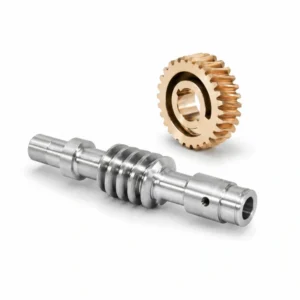
Alloy Steel Worm And Worm Gear for Auto Parts – M0.2-M2.2, ODM
-
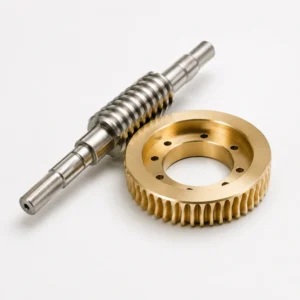
Worm and Wheel – High Precision Brass, M3-M12, 20:1-300:1
-
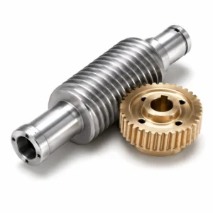
Duplex Worms Gear – Adjustable Backlash, Zero Backlash Precision
-
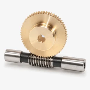
Customized Worm Gear Set – OEM, All Materials, No MOQ
-
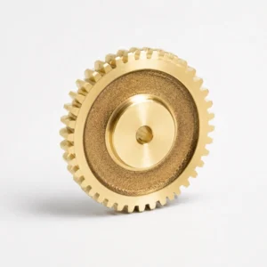
Brass Worm Wheel – M0.5, 20T, Complete Set with Worm Shaft
-
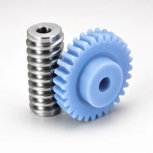
Plastic Worm Gears – POM/Nylon, M0.2-M2.0, Low Noise
-
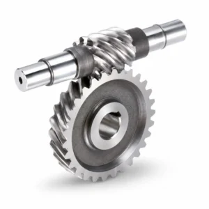
Stainless Steel Worm Gear for CNC Machinery – DIN 5-7, M1-M4
-
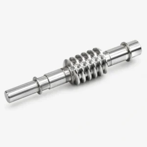
Worm Gear Shaft (Worm Gear Drive Shaft) Customized Worm Shaft
 English
  Italian
  Korean
  French
  Japanese