
Spiral Bevel Gear – Localized Contact, Min 5 Teeth, M3-M12
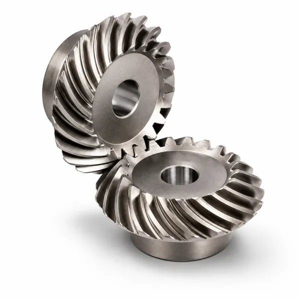
Korea Ever-Power spiral bevel gears transmit power between intersecting shafts with curved teeth that create progressive contact from one end of the tooth face to the other. Controlled localized contact reduces sensitivity to shaft misalignment, minimizes noise and vibration, and allows minimum tooth counts as low as five or six — enabling higher transmission ratios in compact housings. Available in modules M3 through M12 and beyond, in carbon steel, alloy steel, stainless steel, brass, aluminium, and POM. ISO, DIN, ANSI, JIS, BS, and non-standard. Full QA documentation with every order.
Product Overview
A spiral bevel gear has a curved pitch bevel tooth line. Its meshing process differs fundamentally from a straight bevel gear: when two teeth engage, the contact area does not appear simultaneously along the full tooth length. Instead, contact begins at one end of the tooth face and moves progressively across the face toward the other end as the gears rotate. At any moment during engagement, at least two tooth pairs are simultaneously in mesh — this is the overlap coefficient that defines how much of the load the spiral form shares across multiple teeth at once. The result is smoother power transmission, higher load capacity, and significantly lower noise and vibration than a straight bevel or zero-degree spiral bevel gear of the same module and tooth count.
One of the most important engineering characteristics of spiral bevel gears is the ability to control the localized contact area on the tooth surface. By making small, calculated adjustments to the curvature of one or both tooth flanks during gear cutting, the position and shape of the contact zone can be precisely placed on the tooth surface under the expected working load. This localization of contact serves a purpose that is not immediately obvious: it makes the gear set's performance significantly less sensitive to small deviations in shaft and housing geometry during assembly. A gear pair with a precisely localised contact zone will continue to distribute load correctly even when mounting distance, angular alignment, or shaft deflection deviates slightly from the ideal. A gear pair with full-face contact — like a straight bevel pair — is much more sensitive to such deviations, because even small misalignment shifts the contact to the tooth edge, dramatically raising local stress.
Korea Ever-Power spiral bevel gears are manufactured from alloy steel blanks through the full production sequence: blank preparation, gear cutting on dedicated bevel gear generating machines, heat treatment, tooth finishing (lapping or grinding), and full QA inspection. The minimum tooth count achievable on a spiral bevel gear is considerably lower than on a straight bevel — as few as five or six teeth on the pinion — which allows high transmission ratios in compact housing envelopes. Two geometric configurations are available: the standard intersecting-axis type where the large and small gear axes meet at a point, and the hypoid type where the pinion axis is offset from the ring gear axis. Korea Ever-Power produces both.
Localized Contact Control — The Defining Engineering Feature
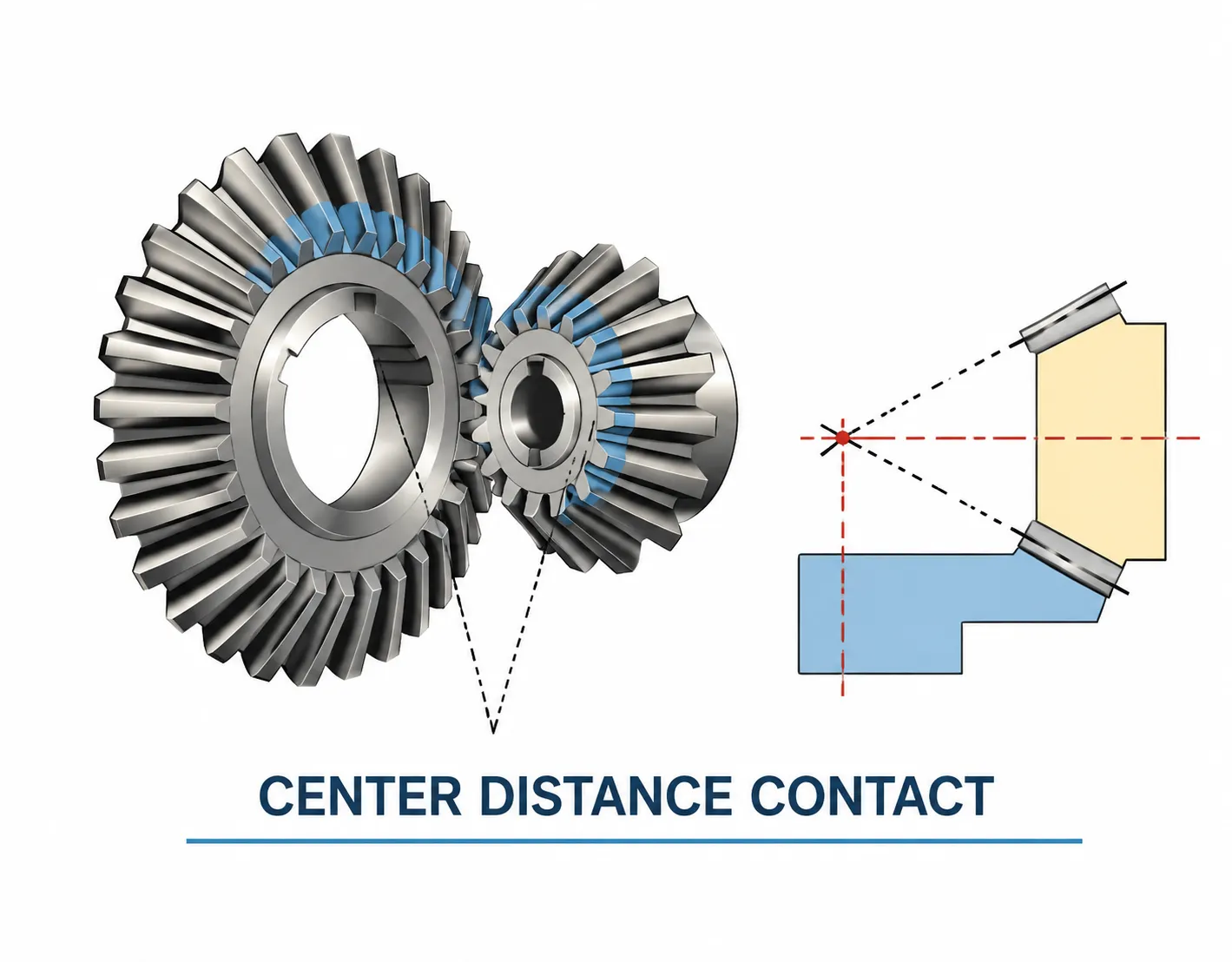
Tooth contact in any bevel gear pair is never perfectly uniform across the full face width in service. Shaft deflection, housing bore tolerances, thermal expansion, and bearing pre-load all cause small deviations from the theoretical gear position. The question is not whether these deviations exist — they always do — but whether the gear set is designed to handle them gracefully.
The localization of contact on a spiral bevel gear is achieved by introducing a controlled amount of mismatch between the theoretical tooth surfaces of the two gears — typically through a slight modification of the cutter radius used for one or both members of the pair. This modification means the two tooth surfaces do not touch at a full line under zero load; instead they touch at a defined area whose position on the tooth face, and whose rate of growth under increasing load, is engineered to remain within the tooth boundaries under all expected service conditions. The position of this contact zone — toward the toe, at mid-face, or toward the heel — can be verified by the blue-print test (engineer's blue applied to the tooth, pair rotated by hand) against the reference contact pattern supplied with the gear set.
What good contact looks like at no-load: The contact print should sit between the toe and the centre of the tooth face, at mid-tooth height. It should not touch any edge — not the toe edge, not the heel edge, not the top land, and not the root fillet. Under full operating load, elastic deflections shift the contact toward the heel and toward the pitch line; the no-load contact zone is offset toward the toe to compensate for this predictable shift. A contact zone already at mid-face or heel under no-load will move to the heel edge under load, causing edge stress and rapid pitting.
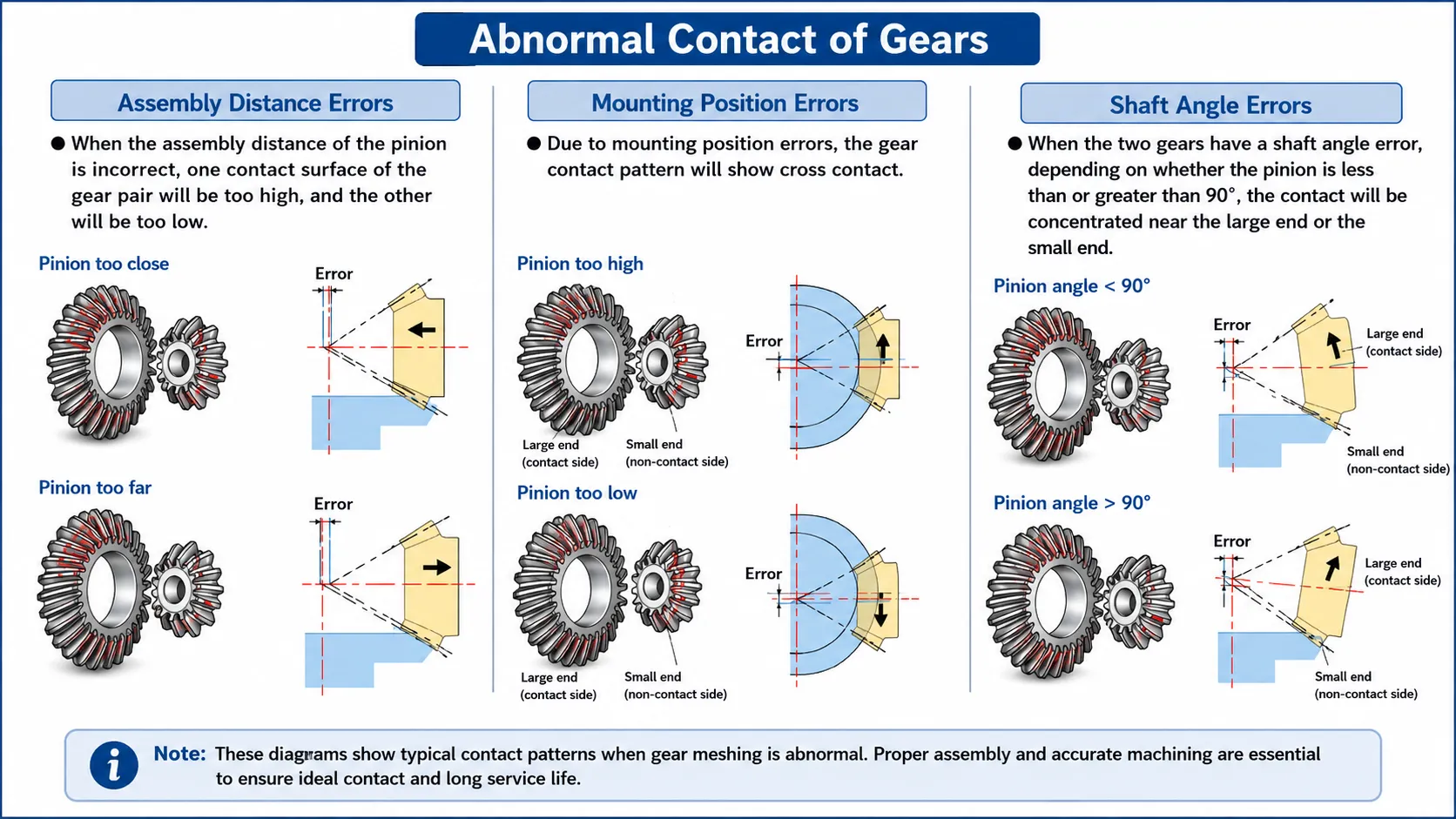
Korea Ever-Power includes a reference contact pattern photograph with every matched spiral bevel gear set, taken under a controlled test load on our roll-test bench before shipment. Comparing this photograph against the contact print in your housing tells you immediately whether the mounting distance and angular alignment are within the acceptable range — and in which direction adjustment is needed if they are not.
Two Configurations — Intersecting Axis and Hypoid Spiral Bevel
Type 1 — Intersecting Axis Spiral Bevel Gear
The large wheel axis and the small wheel (pinion) axis intersect at a common apex point. This is the standard spiral bevel gear configuration used in the majority of industrial gearboxes, agricultural drives, machine tool angle heads, and high-speed printing equipment. Both pitch surfaces are conical and share a common apex. Efficiency is very high — typically 97 to 99 percent per stage — because sliding velocity at the tooth flank is low relative to the rolling velocity. Standard EP gear oil provides adequate lubrication without special hypoid-rated additives.
Typical uses: industrial gearboxes, machine tools, agricultural machinery, printing presses, wind turbine yaw drives
Type 2 — Hypoid Spiral Bevel Gear (Offset Axis)
The pinion axis is offset from the ring gear axis by a defined hypoid offset distance — the axes are in parallel planes but do not intersect. This offset shifts the pinion tooth geometry from a conical to a hyperboloid of revolution, which increases tooth surface area, improves load capacity by up to 30 percent over an equivalent intersecting-axis spiral bevel pair, and allows pinion offset below the ring gear centreline (lowering the vehicle floor in automotive applications). The offset also increases sliding velocity at the tooth flanks, which requires hypoid-rated EP gear oil that can handle the higher sliding without scoring the tooth surface. Efficiency is slightly lower than the intersecting-axis type — typically 90 to 96 percent per stage.
Typical uses: automotive rear axle differentials, heavy truck final drives, off-road vehicle drivetrain
| Criterion | Intersecting Axis (Standard) | Hypoid (Offset Axis) |
|---|---|---|
| Axis arrangement | Axes intersect at apex | Axes offset — do not intersect |
| Efficiency per stage | 97% – 99% | 90% – 96% |
| Tooth contact area | High | Up to 30% higher — more tooth overlap |
| Noise | Low | Slightly lower — greater overlap |
| Ratio range per stage | Up to ~10:1 | Up to ~25:1 |
| Lubrication | Standard EP gear oil | Hypoid-rated EP oil required |
| Packaging benefit | Axes must intersect | Pinion can be below ring gear centreline |
Technical Specifications
All specific values — module, tooth count, spiral angle, contact zone position, bore dimensions, and heat treatment depth — are confirmed against your drawing or application data at the quotation stage before production begins.
| Parameter | Standard Range / Options |
|---|---|
| Gear Type | Spiral bevel gear — intersecting axis or hypoid (offset axis); matched pairs |
| Module (Standard) | M3, M4, M5, M8, M12; other modules per customer drawing |
| Minimum Tooth Count | As low as 5 – 6 teeth on pinion (geometry and ratio dependent) |
| Mean Spiral Angle | Per customer drawing; typically 25° – 40° for industrial applications |
| Pressure Angle | 20° standard; other angles per drawing |
| Shaft Intersection Angle | 90° standard; other angles and hypoid offset per drawing |
| Precision Grade | DIN 6, DIN 7, DIN 8, DIN 9 |
| Manufacturing Standard | ISO, DIN, ANSI, JIS, BS, non-standard; customer drawings accepted |
| Tolerance | 0.001 mm – 0.01 mm – 0.1 mm (grade-dependent) |
| Tooth Treatment | Hardened, milled, or ground; lapped pairs as standard for matched sets |
| Material — Ferrous | C45 carbon steel, alloy steel (40Cr, 42CrMo, 20CrMnTi), stainless steel (304, 316) |
| Material — Non-Ferrous | Brass, copper, aluminium alloy |
| Material — Non-Metallic | POM (acetal), engineering resins (light load applications) |
| Surface Treatment | Zinc-plated, nickel-plated, passivation, black oxide, phosphating, anodisation, Dacromet, powder coating, electrophoresis |
| Contact Zone | Localised contact with reference print photograph supplied for each matched pair |
| QA Documentation | Chemical composition, mechanical performance, UT, heat treatment curve, dimensional inspection report |
Five Common Operating Problems and How to Resolve Them
Even correctly specified and manufactured spiral bevel gears can encounter performance problems during service. The five issues below account for the majority of field complaints. Understanding the root cause of each guides the correct corrective action — and avoids replacing serviceable gears when the problem lies in the lubrication, alignment, or operating conditions rather than in the gear itself.
Gear Noise and Vibration
Root cause: incorrect mounting distance shifting the contact zone to the toe or heel edge; worn tooth flanks; inadequate lubrication film allowing metal-to-metal asperity contact; resonance at a specific speed.
Resolution: verify contact pattern with blue-dye test and compare against the reference print; check mounting distance shims; confirm oil viscosity and EP additive; inspect tooth surfaces for pitting or wear. If noise appears at a specific rpm, investigate resonance of the shaft, housing, or coupled structure at the tooth mesh frequency.
Premature Gear Wear and Tooth Failure
Root cause: overload beyond the gear's rated torque; inadequate lubrication (wrong oil grade, degraded oil, insufficient quantity); contact zone at tooth edge due to mounting error; abrasive contaminants in the oil.
Resolution: confirm actual operating torque against the gear's rated capacity; change oil and inspect for metallic debris or water contamination; verify contact pattern; fit a magnetic drain plug to capture ferrous debris and monitor it as a wear indicator. Consider a surface treatment upgrade — nitriding or DLC coating — if the environment is particularly abrasive.
Shaft and Gear Misalignment
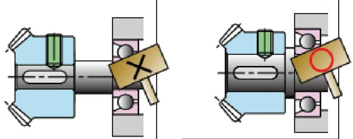
Root cause: housing bore misalignment from machining error or distortion; incorrect shim stack under bearing cups; axial, radial, or angular shaft misalignment exceeding the gear's localised contact tolerance.
Resolution: perform a full contact pattern check with engineer's blue before any load is applied. Axial misalignment is corrected by adjusting shims under the bearing cup to move the gear along its shaft until the contact zone matches the reference print. Angular misalignment requires housing bore correction — shimming cannot correct a housing bore that is machined out of square to the shaft centreline.
Insufficient Lubrication
Root cause: oil level too low; wrong viscosity grade (too thin at operating temperature, or too thick at start-up in cold conditions); oil degraded past its service life; splash lubrication not reaching the gear mesh in certain mounting orientations.
Resolution: confirm oil level is at the large-end tooth depth mark on the dipstick, not below it. Verify the oil grade against the gearbox data plate specification — ISO VG 220 EP for most industrial enclosed spiral bevel drives. Change oil at the specified interval and drain the initial fill at 500 hours to remove running-in debris. For gearboxes operating in orientations where splash lubrication may not reach the mesh, consider a forced lubrication circuit or an oil mist system.
Tooth Chipping and Impact Damage
Root cause: shock loads exceeding the gear's impact capacity — sudden engagement under full load, hard stops, foreign object debris entering the mesh, or resonant torsional oscillation from the driven load.
Resolution: inspect the debris in the oil sump — tooth chip fragments are distinctive in size and shape and confirm the failure mode. Fit a magnetic drain plug and a suction strainer before commissioning any replacement gear. If shock loading is confirmed, consider specifying a case-hardened gear grade with a tougher core material, fitting a torque limiter upstream of the gear set, or reducing the ramp rate of the drive motor start-up cycle. Korea Ever-Power can advise on material grade upgrades if impact resistance needs to be improved on the replacement set.
Applications
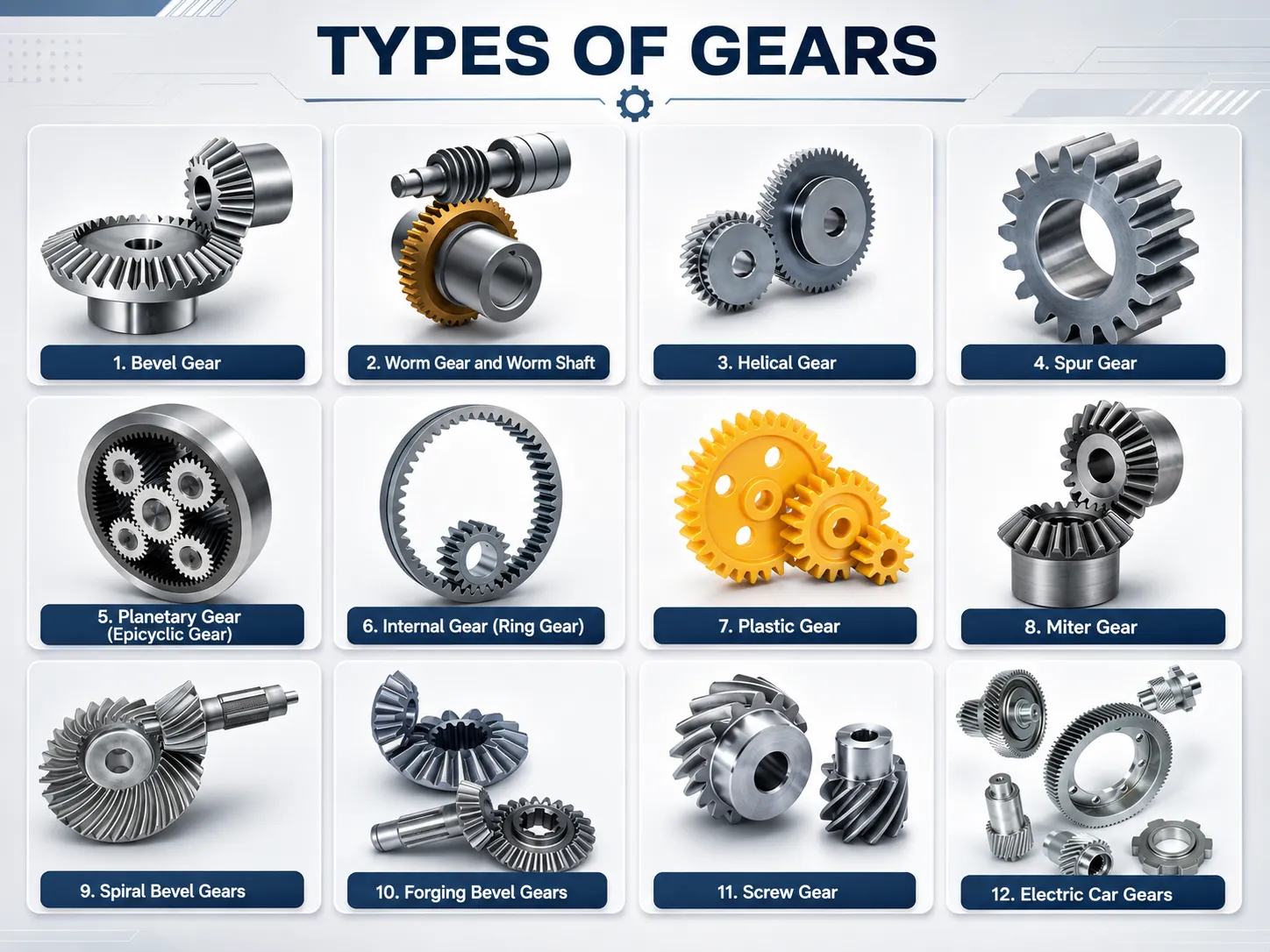
Spiral bevel gears are used across an exceptionally broad field of applications — from 5-tooth high-ratio pinions in automotive differential final drives to large-module industrial gearbox ring gears in mining and power generation. The combination of high overlap coefficient, localised contact tolerance, and mass-production efficiency on dedicated bevel gear machines makes the spiral form the dominant bevel gear type in new designs at moderate to high speed and load.
🚗 Automotive & Vehicle Drivetrain
Rear axle differentials, transfer cases in 4WD vehicles, and heavy truck final drives. The hypoid variant (offset axis) is universal in passenger car rear axles for its load capacity and the packaging benefit of lowering the propeller shaft. Intersecting-axis spiral bevel gears are used in axle differentials for off-road equipment where a higher efficiency and simpler lubricant specification is preferable to the packaging benefit of hypoid geometry.
⛏ Mining & Heavy Industry
Bucket wheel excavators, dredger drives, conveyor head drives, and mill drives transmit very high continuous torques through spiral bevel stages. Large-module gears in alloy steel with full material certification, UT inspection, and hardness verification are standard for mining sector applications where a gear replacement requires a full equipment shutdown.
✈ Aviation & Defence
Helicopter tail rotor drives, aircraft engine accessory gearboxes, and military vehicle final drives use high-precision spiral bevel gears in aerospace-grade steel. The localised contact characteristic is especially valuable in helicopter applications where gearbox housing deflection during manoeuvres must not shift the tooth contact zone to the edge.
⚙ Industrial Gearboxes
Right-angle gearboxes for conveyors, agitators, compressors, and mixer drives predominantly use spiral bevel stages above a few kilowatts of power where the efficiency advantage over worm gears outweighs the higher gear cost. Over a 10-year service life, the energy saved by a spiral bevel stage at 98 percent efficiency versus a worm stage at 85 percent is substantial for any drive above approximately 5 kW.
📷 Printing & Packaging
High-speed offset printing presses and packaging machines use spiral bevel gears at pitch-line speeds where straight bevel gears would generate unacceptable noise and vibration. The localised contact also reduces the transmission error that would otherwise show up as a repeating position defect in the printed product or packaged item. Ground tooth variants with DIN 6 accuracy are standard for high-speed press cross-drives.
🚑 High-Speed Rail
Traction motor final drives and bogie bevel gear stages in high-speed rail vehicles require spiral bevel gears that maintain low noise and vibration across a wide speed range, from station stop to line speed. Full material traceability, UT inspection, and compliance with applicable rail standards are required for new production gears, and Korea Ever-Power provides this documentation package as standard for rail sector orders.
Quality Assurance & Testing
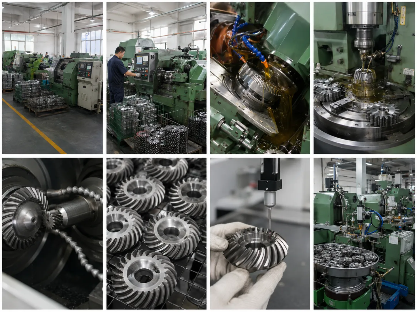
Korea Ever-Power applies a comprehensive quality assurance sequence to all spiral bevel gear production. Every batch ships with the following documentation:
- Chemical composition report — mill cert and independent spectral analysis confirming steel grade and chemistry match the specified material before any machining begins.
- Mechanical performance report — tensile strength, yield strength, elongation, and impact toughness on test pieces from the same heat as production parts.
- Ultrasonic test (UT) — 100% UT per EN 10228-3, SA388, or the customer-specified standard, performed on the blank before gear cutting to detect internal voids, inclusions, or segregation. This is a selectable option confirmed at the quotation stage; standard for mining, aviation, and rail applications.
- Heat treatment report — original time-temperature curve from the furnace run, retained per batch as evidence that the hardening cycle met specification. Carburising depth verified by cross-section metallographic inspection on sample pieces.
- Dimensional inspection report — CMM measurement of pitch cone angle, tooth spacing error, runout, spiral angle, bore, OD, and face width against drawing tolerances.
- Roll-test contact pattern photograph — each matched pair is run on our roll-test bench under controlled load and the contact zone position photographed and filed against the order number. This photograph is the reference for installation contact pattern verification at the customer's assembly.
Frequently Asked Questions
What does "localised contact" mean and why does it matter?
Localised contact means the contact zone between two meshing spiral bevel gear teeth is confined to a defined area on the tooth face rather than extending across the full face width under all conditions. This is achieved by deliberately introducing a controlled mismatch between the theoretical tooth surfaces, usually by modifying the radius of curvature of one or both tooth flanks during gear cutting. The purpose is tolerance: a gear set with localised contact continues to load the tooth face correctly even when the housing bore, shim stack, or shaft deflects by small amounts from the ideal position. A full-face contact gear set is much more sensitive — any deviation pushes the contact toward the tooth edge, concentrating stress and accelerating pitting. Localised contact is what makes spiral bevel gears reliable in real-world assemblies rather than only in theoretical perfect geometry.
Why can spiral bevel gears use fewer teeth than straight bevel gears at the same ratio?
The minimum tooth count on any gear is limited by undercutting — the condition where the tip of the mating gear tooth removes material from the root fillet of the gear being cut, weakening the tooth. The minimum tooth count before undercutting depends on the pressure angle and, for bevel gears, on the spiral angle. A spiral bevel gear has an effective pressure angle at the mean cone distance that is larger than the nominal pressure angle as seen in the axial cross-section, because the spiral angle contributes an additional component to the tooth geometry. This larger effective pressure angle allows a smaller tooth count before the undercutting threshold is reached. The result is that a spiral bevel pinion can carry as few as five or six teeth at ratios where a straight bevel pinion would need ten or more, enabling a more compact and higher-ratio gearset in the same housing.
How do I know whether I need an intersecting-axis spiral bevel or a hypoid gear?
If the two shaft centrelines in your gearbox intersect at a point, you need an intersecting-axis spiral bevel gear. If the shaft centrelines are in separate parallel planes with a defined offset distance between them, you need a hypoid gear. In practice, the choice is usually determined by the housing design: if an existing housing is designed for hypoid, replacing with intersecting-axis geometry would require a new housing. For a new design, choose intersecting-axis (standard spiral bevel) unless you specifically need the packaging advantage of axis offset — lowering the propeller shaft in a vehicle, or routing a shaft past an obstacle — or require the higher load capacity that the hypoid geometry provides at the same outer diameter. Also note that hypoid gears require a specifically formulated hypoid-rated EP gear oil, adding a lubricant specification constraint that intersecting-axis spiral bevel gears avoid.
The gear runs noisily but the tooth flanks look undamaged. What should I check first?
Noise without visible tooth damage almost always points to one of three causes: incorrect mounting distance, wrong lubricant viscosity, or a resonant vibration at tooth mesh frequency. Check mounting distance first — perform the blue-dye contact test and compare against the reference pattern. If the contact sits at the heel, reduce mounting distance by removing shims under the bearing cup of the gear that shows heel contact; if it sits at the toe, add shims. If the contact pattern is correct but noise persists, verify the lubricant grade and oil level. If both are correct, measure the noise frequency: tooth mesh frequency equals the number of teeth multiplied by shaft rpm divided by 60. If the noise frequency matches a structural resonance of the shaft, housing, or connected machinery, the solution is a stiffness or mass change to the resonant structure rather than anything in the gear set.
Must spiral bevel gears always be replaced in matched pairs?
Yes, for lapped spiral bevel gear sets. The contact zone on a lapped pair is optimised by running the specific ring gear and pinion together with abrasive compound during the lapping stage, fine-tuning the contact pattern to sit correctly on both members simultaneously. This optimisation belongs to that specific pair — fitting a new pinion to an old ring gear produces a contact pattern that neither member was produced for. The new pinion will wear in a way that compensates for the old ring gear's surface, but it may never achieve the contact quality of a properly matched set, and the resulting noise and contact stress may exceed the original design intent. Replace lapped spiral bevel gear sets as complete matched pairs.
What information does Korea Ever-Power need to produce a replacement spiral bevel gear set?
The ideal submission is the original drawing plus both gears of the worn pair. From the drawing we extract module, tooth count, spiral angle, pressure angle, pitch cone angle, and bore and hub dimensions. From the worn gears we verify the module and spiral angle by direct measurement, which also reveals any discrepancy between the drawing and the as-made geometry. If no drawing is available, send both gears and provide the outer diameter, face width, tooth count, bore, hub length, and hub diameter of each. Our engineering team measures the spiral angle from the sample, calculates the full geometry, and issues a production drawing for your approval before cutting begins. For hypoid gear sets, the pinion offset distance is a critical additional dimension — it can be measured from the worn gears if the housing is available for measurement, or estimated from the housing bore position if the gears alone are submitted. Send us your enquiry and we will advise on the fastest route to a correct replacement set for your specific situation.
Customer Reviews
"We overhauled a mining bucket wheel slewing drive that had run 14,000 hours. The worn spiral bevel pair showed heel contact on the ring gear tooth — a classic mounting distance error that had been present since the original installation. Ever-Power supplied the replacement set with a tighter mounting distance recommendation and a reference contact print at the correct position. After installation with the corrected shim stack, the drive runs quieter than it did when new."
Ryu Sang-min | Plant Maintenance Manager, Gangwon Mining Operations · Q1 2026
"We design industrial right-angle gearboxes and switched from worm stages to spiral bevel gear stages across our 5 kW to 30 kW product range three years ago. Energy savings for our customers average 12 to 18 percent on continuous-duty drives. Ever-Power supplies the spiral bevel pairs with consistent contact pattern quality across batches — the roll-test photograph they include has matched our incoming inspection result on every delivery."
Choi Hyeon-jun | Product Engineering Manager, Incheon Gearbox Manufacturing · Q3 2025
"We replaced a hypoid spiral bevel pair in a commercial vehicle rear axle. The hypoid offset dimension was critical and not marked on the worn gears. Ever-Power measured it directly from the housing bore position we provided in a dimensioned sketch. The replacement pair fitted the axle housing correctly and the oil specification was confirmed as hypoid-rated EP, which the previous service provider had ignored — likely the cause of the original failure."
Oh Tae-soo | Service Technician Lead, Busan Commercial Vehicle Maintenance · Q4 2025
"We had tooth chipping in a conveyor head spiral bevel stage during winter start-up — low oil temperature and an undersized motor start ramp were the root cause. Ever-Power supplied the replacement set with a case-hardened 20CrMnTi specification replacing the original through-hardened grade. No further chipping in two subsequent winter seasons. The material upgrade recommendation from their application team was accurate."
Jung Seok-woo | Engineering Supervisor, Gyeongnam Logistics Centre · Q2 2025
"We manufacture high-speed printing press cross-drives and specify DIN 6 ground spiral bevel gears for register accuracy. The contact pattern quality from Ever-Power is consistent from batch to batch — the roll-test photograph shows the contact zone at the correct toe-to-centre position every time. In 30 months of production supply, we have not needed to re-adjust a single press after a gear replacement."
Nam Hyun-ki | Drive Systems Engineer, Seoul Press Technology Co. · Q1 2026
Request a Quotation for Spiral Bevel Gears
Send us your drawing, worn gear pair, or application data — module, tooth count, spiral angle, bore, and material. For hypoid sets, include the pinion offset dimension or a housing bore sketch. Our engineering team returns a feasibility review and price within two working days. Roll-test contact pattern photograph included with every matched pair.
Additional information
| Editor |
|---|
Related products
-
Straight Bevel Gear – M3 to M12, DIN6-9, Multi-Material
-
Metal Bevel Gear – M0.15 to M2.0, 11 Alloys, AGMA 13
-
Aircraft Bevel Gear – M0.15 to M2.2, AGMA 13, AS9100
-
Bevel Gears European Standard – DIN Type A & B, 1:1 to 1:4
-
Spiral Miter Gears – 35° Spiral Angle, 1:1 High-Speed Drive
-
90 Degree Bevel Gears – Right-Angle Drive, All Materials
-
Sintered Metal Bevel Gears – Self-Lubricating, DIN 6–9
-
Precision Bevel Gear – M0.15 to M2.2, AGMA 13, 5 HT Routes
 English
  Italian
  Korean
  French
  Japanese