
Bevel Gears European Standard – DIN Type A & B, 1:1 to 1:4
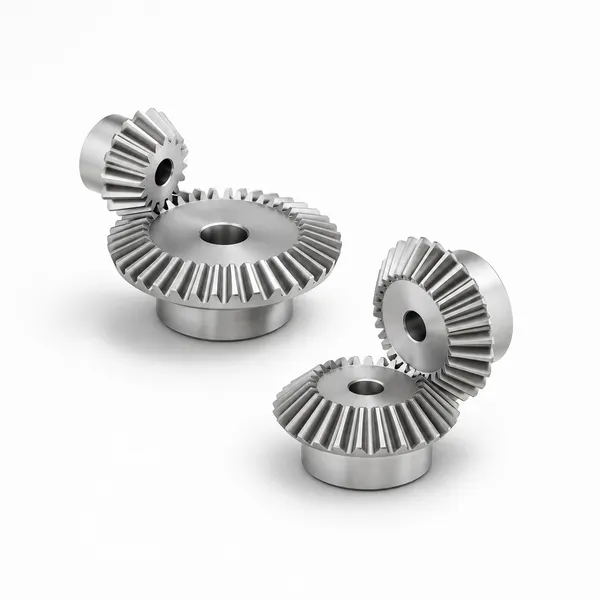
Korea Ever-Power European standard bevel gears are produced to DIN specifications in Type A and Type B configurations, covering gear ratios 1:1 through 1:4. Conical tooth profiles on intersecting shafts allow compact right-angle or angular power transmission in automotive, industrial, and power-tool applications. Steel, cast iron, and non-ferrous material options; straight and spiral tooth forms available; full dimensional and hardness documentation with each order.
Product Overview
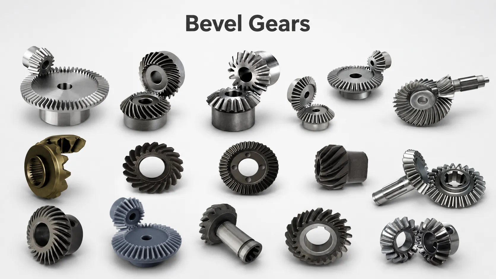
Korea Ever-Power European standard bevel gears are dimensioned and tolerance-rated to DIN specifications, covering Type A and Type B configurations in gear ratios from 1:1 through 1:4. A bevel gear is defined by its conical pitch surface: unlike spur or helical gears whose teeth run parallel to the rotation axis on a cylindrical surface, bevel gear teeth are cut on a cone, and two meshing bevel gears share a common apex point where their pitch cone axes intersect. This geometry is what allows bevel gears to transmit rotation and torque between shafts that meet at an angle — most commonly 90°, but other intersection angles are achievable with appropriate cone angles on each gear.
The European standard (DIN) defines both the tooth geometry and the dimensional system used to specify bevel gears across the metric module series. Buyers sourcing replacements for existing European-designed machinery, or designing new equipment intended to comply with DIN standards for the European market, need gears produced to these specifications rather than to AGMA or JIS tables. Korea Ever-Power produces DIN-conforming bevel gears as standard production items, with dimensional verification against DIN 3971 tooth geometry and DIN 3975 accuracy class requirements.
Both Type A and Type B housings have distinct mounting face arrangements and bore configurations that determine how the gear locates within its gearbox housing. The correct type must be specified at the quotation stage based on the housing design. Korea Ever-Power's engineering team can review your housing drawing and confirm the correct type and dimensions before production, eliminating fit problems at assembly. For the full range of bevel gear types available — including spiral, miter, and zero-degree variants — see the product category page.
Working Principle of Bevel Gears
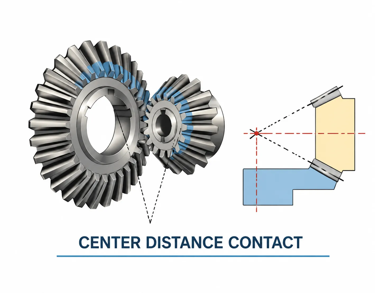
Power transmission in a bevel gear pair works on the principle of conjugate tooth action between two conical pitch surfaces. When the two gears rotate, their teeth mesh along a contact line that sweeps across the tooth face from the small end (toe) toward the large end (heel). The line of contact is not parallel to either shaft axis, which is why the geometry must be treated as a cone-section problem rather than a simple cylindrical one.
The pitch cone angle of each gear in a pair determines how much of the full 90° intersection angle each gear contributes. For a 1:1 ratio (miter gear), both gears have a pitch cone angle of 45°. For a 1:2 ratio, the pinion has a pitch cone angle of approximately 26.6° and the ring gear approximately 63.4°. These angles are fixed by the ratio and cannot be adjusted independently, which is why specifying the gear ratio precisely is the first step in any bevel gear selection.
The tooth profile of a straight bevel gear traces an involute on the back cone, which is a plane perpendicular to the pitch cone surface at the large end of the tooth. For European standard bevel gears, the reference profile is a standard 20° pressure angle involute on the back cone. The tooth depth decreases from heel to toe in proportion to the cone distance, which means the tooth is thicker at the large end and tapers toward the small end — a geometrically necessary consequence of the conical pitch surface.
Technical Specifications
The table below describes the general production capability and standard configuration options for Korea Ever-Power European standard bevel gears. All specific values — module, tooth count, bore, face width, and heat treatment depth — are confirmed against your drawing or application data at the quotation stage.
| Parameter | Typical Range / Options |
|---|---|
| Standard | European standard (DIN 3971 tooth geometry; DIN 3975 accuracy) |
| Configuration | Type A and Type B (per housing and mounting face arrangement) |
| Gear Ratios | 1:1, 1:2, 1:3, 1:4 standard; other ratios per drawing |
| Tooth Form | Straight bevel (standard); spiral bevel available on request |
| Pressure Angle | 20° standard per DIN reference profile |
| Shaft Intersection Angle | 90° standard; other angles per drawing |
| Module | Metric module series per DIN; confirmed with order specification |
| Material (Standard) | C45 (equivalent to 45# steel), 42CrMo4, 20MnCr5, 16MnCr5 |
| Material (Optional) | GJL-250 grey cast iron, EN1.4301 (304) stainless, brass, bronze |
| Heat Treatment | Case-hardening (carburising + quenching), through-hardening, normalising, nitriding |
| Tooth Finishing | As-cut (normalised); lapped or ground for higher accuracy grades |
| Surface Treatment | Phosphating, black oxide, zinc plating, as-machined |
| Machining Standard | DIN primary; AGMA and JIS equivalents available on request |
| Certification | ISO 9001:2015; material cert and hardness report with each order |
Type A and Type B Configurations
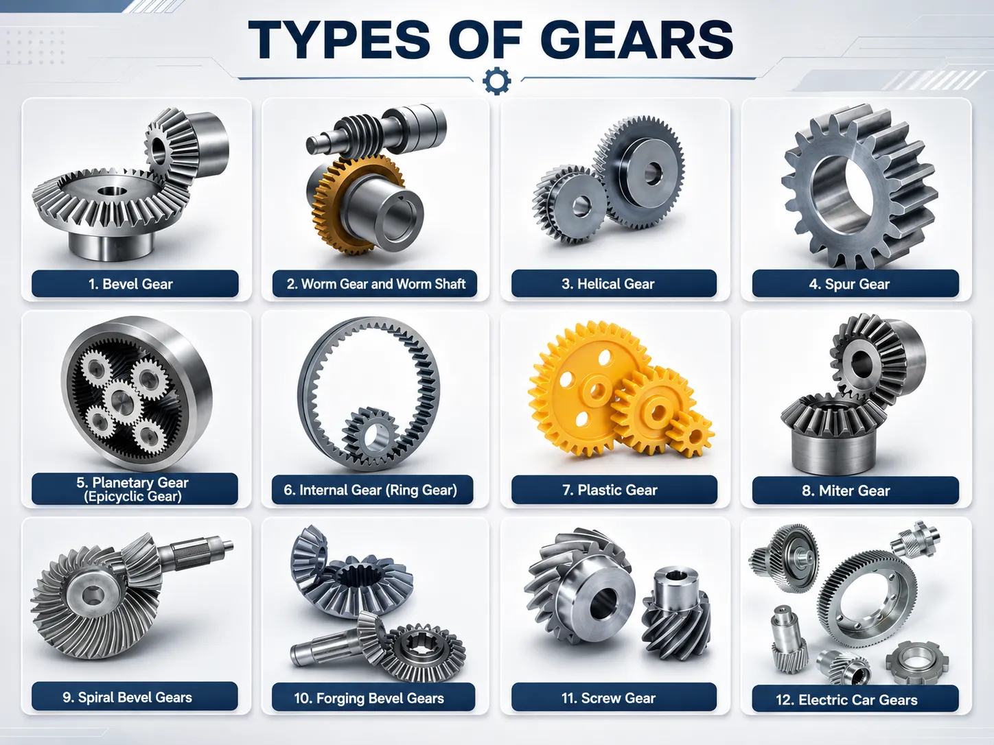
The European standard bevel gear series defines two primary housing and mounting configurations. Specifying the wrong type is one of the most common ordering errors, because the outer dimensions of the gear body may look similar while the bore and back-cone face arrangement differ. The following describes the key distinction:
Type A
Type A bevel gears are the standard configuration for most enclosed gearbox applications. The gear body includes a hub that protrudes to one side of the pitch cone back face. The bore runs through the hub centrally. Mounting face and hub length dimensions are defined by the DIN series and are interchangeable with other manufacturers' Type A gears of the same module and ratio, which is significant for users sourcing replacements for European-designed gearboxes.
Common in: industrial gearboxes, conveyor drives, agricultural machinery, general-purpose right-angle drives
Type B
Type B bevel gears have a different hub geometry and back-cone face arrangement suited to applications where space behind the gear is constrained, or where the gear must be mounted flush against a housing wall without a projecting hub. The bore and keyway arrangement follows the DIN series for the relevant module. Type B should be specified when the original gearbox drawing or the housing configuration calls for it explicitly — substituting Type A where Type B is specified will result in an incorrect fit.
Common in: compact drives, power tools, instrumentation gearboxes, space-constrained mechanical assemblies
If you are unsure which type applies to your housing, share a photograph or sketch of the housing bore and the mating gear's back-cone face arrangement with your enquiry. Our engineering team identifies the correct type from this information and confirms before production.
Key Advantages of Bevel Gears
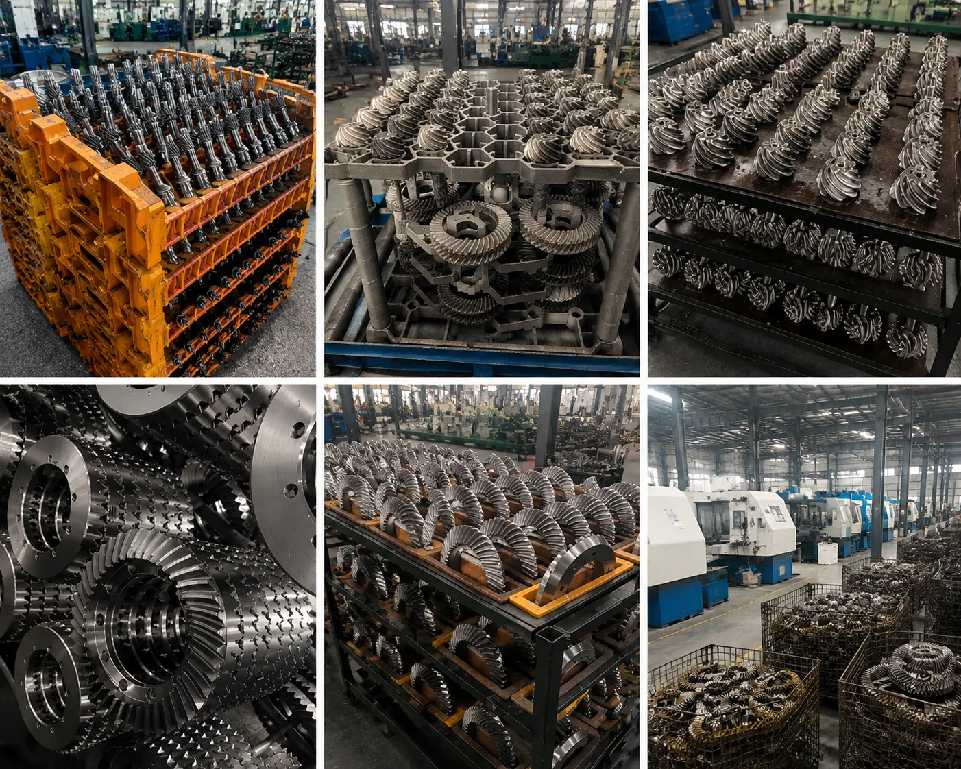
Bevel gears offer a distinct set of mechanical characteristics that make them the preferred solution for angular power transmission in a wide range of industries. The following summarises why designers specify bevel gears over alternative solutions such as worm gears, crossed-axis helicals, or universal joint arrangements:
- Angular power transmission — the only gear type that efficiently changes drive direction between intersecting shafts. Alternative solutions (worm, belt-and-pulley, bevel-planetary combos) all carry trade-offs in efficiency, size, or cost that bevel gears avoid in the 90° right-angle case.
- Compact design — bevel gears deliver the direction change and torque multiplication within the cone geometry, requiring less housing volume than a worm gear pair of equivalent power rating.
- High efficiency — straight and spiral bevel gears operate at 97 to 99 percent mechanical efficiency per stage under full load. Worm gears at equivalent reduction ratios rarely exceed 90 percent, and the lost energy appears as heat that must be managed by the housing and lubricant system.
- High load capacity — the tooth-face-width of a bevel gear is sized to carry the full design torque, and the conical geometry distributes stress across the face in a predictable way that is well-captured by AGMA and DIN stress calculations. Bevel gears handle shock loads and reverse loading better than worm stages of equivalent power rating.
- Smooth operation — spiral bevel gears especially provide smooth, low-vibration operation through progressive tooth engagement. Even straight bevel gears at moderate pitch-line speeds operate with less noise than equivalent worm stages.
- Easy maintenance — lubrication and periodic tooth-wear inspection are the primary maintenance tasks. Neither requires disassembly of the complete gearbox in most designs, and the tooth wear pattern is visible on inspection without special instruments.
Manufacturing Process
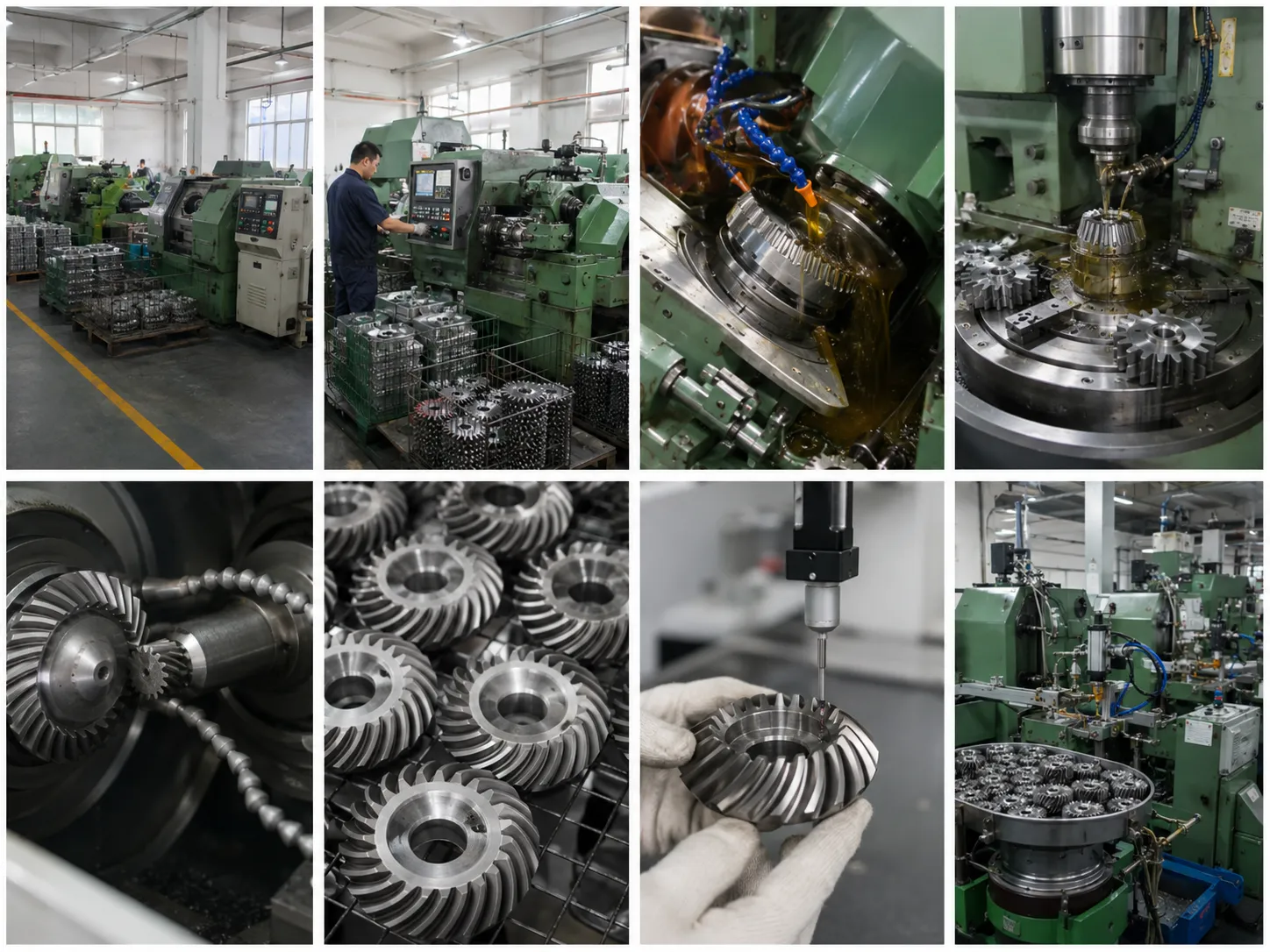
Korea Ever-Power produces European standard bevel gears through the following sequence. Each step generates process records that accompany the order documentation.
Gear ratio, module, pitch cone angle, tooth depth, back-cone distance, and face width are calculated from the application requirements. For standard DIN ratios, these values follow the published DIN series tables; for custom ratios, our engineering team performs the full geometric calculation and issues a dimension sheet for customer approval before cutting begins.
The appropriate steel grade or other material is selected and the gear blank is prepared by forging or bar-stock machining to pre-gear dimensions. Material certificates are checked at incoming inspection. For case-hardening grades, the blank is normalised to relieve internal stress before gear cutting. Cast iron blanks for low-speed applications are prepared by rough machining to remove casting skin before the tooth-cutting stage.
Straight bevel teeth are generated using the Gleason or Coniflex methods on bevel gear generating machines. The Gleason method uses a rotating cutter and a generating process that creates the tooth profile by rolling the blank against the cutting tool — the tooth form emerges from the relative motion rather than being simply copied from a template. The Coniflex method uses a curved cutter that can generate both the tooth profile and the tooth depth in a single setup, which reduces setup time for small batches.
After gear cutting, parts undergo the specified heat treatment. Carburising and quenching produces a hard case over a tough core, which is the standard for gears in industrial and automotive gearboxes. Through-hardening provides uniform hardness for shock-loaded applications. Time-temperature curves for each batch are retained and available on request. Case depth is verified by cross-section metallographic inspection on sample pieces from each batch.
Depending on the required accuracy class, tooth finishing is performed by lapping (running the pair together with abrasive compound to optimise contact pattern and reduce surface roughness), gear grinding (for high-accuracy grades requiring tight transmission error and surface finish targets), or honing. Bore and mounting face final machining is performed after heat treatment to correct any distortion introduced during hardening.
Finished gears are inspected for tooth spacing error, pitch cone angle, runout, bore diameter, and surface hardness. Gear roll testing under load with contact pattern photography is performed on matched pairs. All dimensional and hardness data is recorded per order number and included with the shipment. Surface treatment — phosphating, black oxide, or zinc plating — is applied after final inspection where specified.
Bevel Gears vs. Other Gear Types
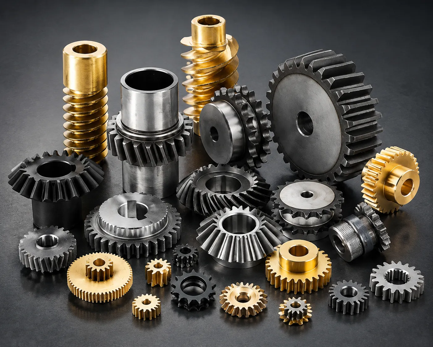
When a designer needs to change shaft direction, several gear types are available. The table below compares bevel gears against the main alternatives on the criteria that matter most in practice.
| Criterion | Bevel Gear | Worm Gear | Crossed-Axis Helical | Spur / Helical (parallel) |
|---|---|---|---|---|
| Shaft arrangement | Intersecting axes | Non-intersecting, non-parallel | Non-intersecting, non-parallel | Parallel axes only |
| Efficiency per stage | 97% – 99% | 70% – 90% (ratio-dependent) | ~90% – 95% | 98% – 99.5% |
| Load capacity | High (line contact) | Moderate | Low (point contact) | Very high |
| Noise level | Low–moderate (spiral: low) | Very low | Low | Low (helical) / moderate (spur) |
| Self-locking | No | Yes (at low lead angles) | No | No |
| High ratio in one stage | Up to ~10:1 | Up to 100:1 | Up to ~10:1 | Typically up to ~6:1 |
| Axial thrust | Yes — on both shafts | Yes — primarily on worm shaft | Yes | Helical: yes; spur: no |
| Best use case | Efficient right-angle drive, moderate-to-high torque | High ratio, self-locking, low power | Lightly loaded angular drives | Parallel shaft, maximum efficiency |
The comparison makes the position of the bevel gear clear: it is the right choice when the shafts genuinely intersect and the application needs high efficiency and high load capacity at the same time. The worm gear's self-locking property and very high single-stage ratio are advantages that bevel gears cannot replicate, but the efficiency penalty of a worm stage is substantial at high power levels. For any drive above approximately 2 kW where a right-angle direction change is needed and self-locking is not required, a spiral bevel stage will almost always deliver a lower total lifetime cost than a worm stage of the same power rating.
How to Select the Right Bevel Gear
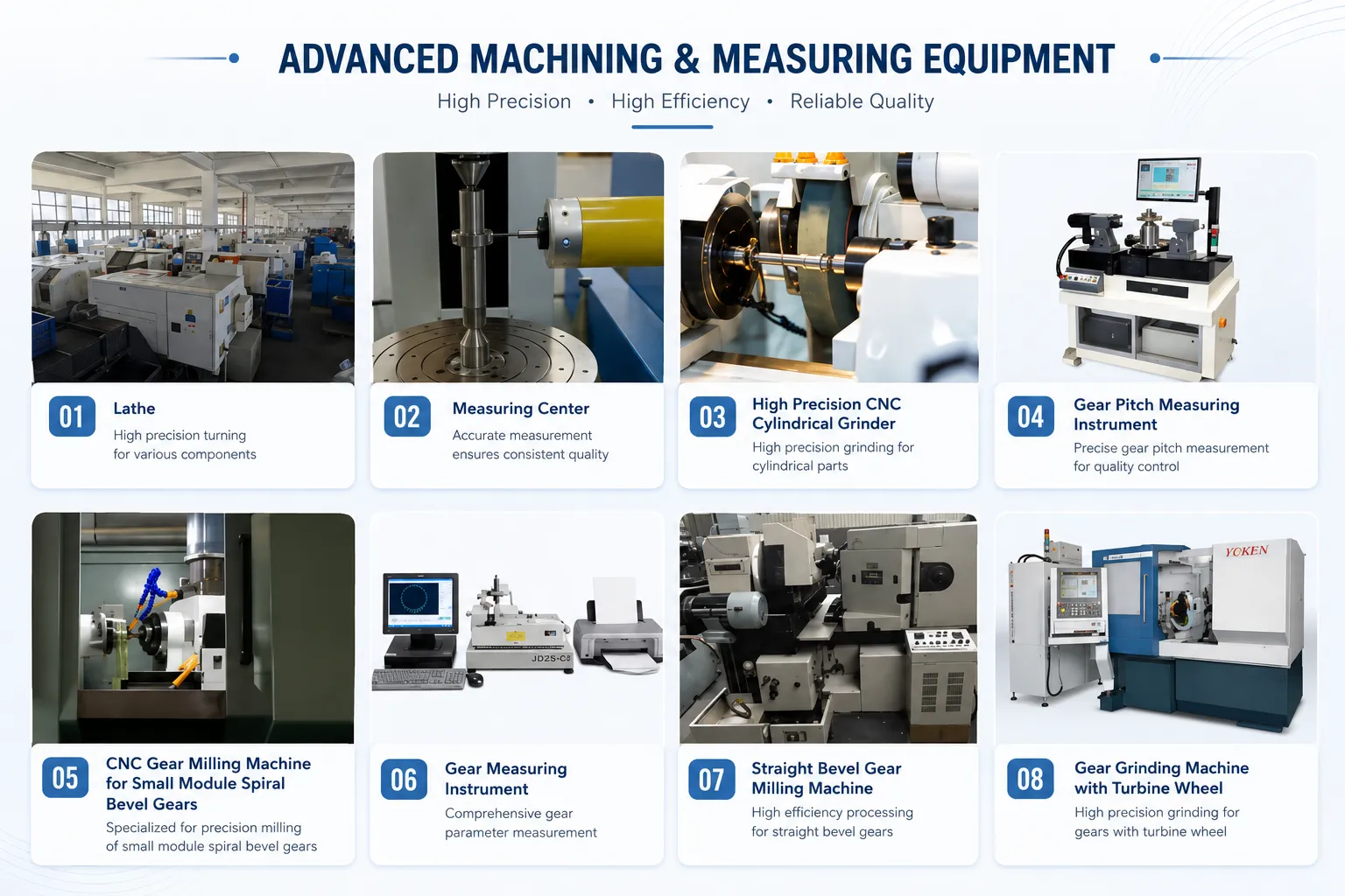
Selecting the correct bevel gear for a European standard application involves working through the following criteria in order. Skip any step that is already defined by the existing housing or system design:
- Gear ratio — determine the required speed ratio between the two shafts. For DIN standard series this will be 1:1, 1:2, 1:3, or 1:4; other ratios require a custom gear pair.
- Type A or Type B — identify the housing type from the original equipment drawing or by measuring the existing gear's hub geometry and back-cone face arrangement.
- Module — calculated from the torque and speed requirements using standard DIN bending and contact stress formulas, or taken from the original equipment data sheet. Do not estimate module from a worn gear by measurement alone — worn teeth give systematically low module readings.
- Tooth form — straight bevel for low-speed or reversing drives; spiral bevel for continuous high-speed operation or where noise is constrained.
- Material and heat treatment — case-hardening alloy steel for maximum load capacity; through-hardening for shock loads; grey cast iron for large, slow drives where cost dominates; stainless steel for corrosive or food-contact environments.
- Accuracy class — DIN quality class 8 or 9 for general-purpose drives; class 6 or 7 for higher speed or low-noise requirements; class 5 for precision instrument drives.
- Surface treatment — phosphating or black oxide for corrosion protection in enclosed housings; zinc plating for outdoor or damp environments; as-machined for stainless steel or applications where dimensional change from plating is a concern.
Frequently Asked Questions
What does "European standard" mean for bevel gears and why does it matter?
European standard bevel gears follow the DIN (Deutsches Institut für Normung) dimensional and accuracy system, which uses the metric module to define tooth size and the DIN 3971 / DIN 3975 standards to define tooth geometry and accuracy grades. This matters because European-designed gearboxes and machinery are dimensioned and specified in DIN terms — module, DIN quality class, and Type A or Type B hub configuration. A replacement gear sourced in AGMA diametral pitch will have different tooth dimensions for the same physical gear size, and cannot mesh correctly with the original mating gear. If you are replacing a gear in a European-origin machine, specifying European standard (DIN) is the only way to ensure geometric compatibility.
How do I identify the module of an existing DIN bevel gear?
The most reliable method is to find the original drawing or gearbox data plate, which will state the module directly. If neither is available, the module can be calculated from the outer diameter and tooth count: for a straight bevel gear, the outer (large-end) pitch diameter equals the module multiplied by the tooth count, so module = pitch diameter / tooth count. The tooth count is easy to count; the pitch diameter requires more care because it is not the same as the outer diameter — the tooth addendum must be subtracted. For a worn gear, this calculation tends to underestimate the module slightly because the addendum has been reduced by wear. When in doubt, send us a sample gear or a detailed sketch with outer diameter, hub diameter, hub length, tooth count, and face width measured, and we will identify the module and confirm the DIN series.
Can I use a straight bevel gear where a spiral bevel gear is currently installed?
Only if the original machine design allows it. Straight and spiral bevel gears of the same module, ratio, and outer diameter are not directly interchangeable — the tooth profile, contact pattern, and face-width geometry differ between them. More importantly, if the housing was designed for a spiral bevel gear at elevated speed, the noise and vibration levels from a straight bevel replacement will exceed the original design intent and may indicate the machine is running outside its design parameters. The reverse substitution — fitting a spiral bevel where a straight bevel was used — is mechanically possible if the housing geometry and shaft arrangement match, but the thrust loads on the bearings will change in magnitude and direction. Always consult the original gearbox specification before substituting tooth form.
What lubricant is recommended for enclosed DIN bevel gearboxes?
For most enclosed European standard bevel gearboxes running at moderate speed and ambient temperatures between 10°C and 40°C, ISO VG 220 gear oil with a GL-4 EP additive is the standard starting point. Gearboxes running hotter than 80°C, or at pitch-line speeds where churning loss is a concern with a heavier grade, benefit from a synthetic PAO gear oil of equivalent or lighter viscosity that maintains viscosity index over the operating temperature range. The gearbox original equipment documentation will usually specify the lubricant grade; for DIN-standard gearboxes this is often expressed as CLP 220 or CLP 320 per DIN 51517 Part 3, which maps to the ISO VG grade and EP additive requirement.
Do you stock standard DIN bevel gears or produce to order?
Korea Ever-Power produces to order rather than holding finished stock. This approach allows us to confirm the exact module, bore size, keyway, and tooth form for each customer's specific housing before production, which eliminates the fit and dimensional problems that arise from adapting a stocked gear to a housing it was not dimensioned for. Lead times for standard DIN series gears in common modules are typically shorter than for completely custom designs. Contact our team with your module, ratio, Type A or B, bore, and material requirement for a lead time estimate.
What documentation comes with each order of European standard bevel gears?
Every order ships with a material certificate confirming the steel grade and chemical composition, a heat treatment record, a dimensional inspection report covering pitch cone angle, tooth spacing error, runout, and bore, and a surface hardness test report at tooth flank and root. For matched pairs, a gear roll test contact pattern photograph is included. Additional non-destructive testing documentation — magnetic particle inspection or dye-penetrant — can be added at the quotation stage for safety-critical applications.
Can Korea Ever-Power supply both gears in a matched pair, or just one?
We supply both single gears and matched pairs depending on the application. For straight bevel gears at low to moderate speed, individual gears can be supplied since the contact pattern is largely determined by the mounting distance rather than by lapping. For spiral bevel gears, the ring gear and pinion should always be replaced as a matched pair because the contact pattern is optimised during the lapping stage for that specific pairing — mixing a new pinion with an old ring gear, or vice versa, will produce an inferior contact pattern and shorter service life. When in doubt, replace the pair. Send us your enquiry with the worn gear's measurements and we will advise on the best approach for your situation.
Customer Reviews
"We maintain a fleet of European-origin conveyors fitted with DIN bevel gearboxes. Sourcing replacement gears locally used to mean long waits for European imports. Ever-Power identified the correct module and Type A configuration from our sample gear, matched the DIN dimensions, and delivered with full material documentation. The gears fit and run correctly — no adjustment needed."
Oh Sang-woo | Maintenance Manager, Gyeongnam Logistics Centre · Q3 2025
"We design packaging machines for the food industry and specify DIN bevel gear pairs throughout. Ever-Power supplies 316L stainless sets to our drawings at a reliable lead time. The dimensional reports they send match our incoming inspection measurements every time. Three years into the supply relationship, not one gear has been returned for quality reasons."
Jung Eun-ji | Lead Mechanical Engineer, Seoul Food Machinery Co. · Q1 2026
"We needed a Type B bevel gear set in a non-standard 1:3 ratio for a conveyor head drive rebuild. The original European supplier's lead time was 14 weeks. Ever-Power produced the set to our DIN drawing, with heat treatment and hardness certification, in under five weeks. The gearbox has been back in production without issue."
Bae Jun-seo | Plant Reliability Engineer, Ulsan Chemical Plant · Q2 2025
"We import German-designed mixing equipment and sometimes need to source replacement gears when the original manufacturer's delivery is too long. Ever-Power cross-referenced our module and DIN configuration accurately on the first quotation. The replacement gears were installed into the original housings without modification and passed our standard operational test."
Yoo Tae-yang | Equipment Manager, Incheon Chemical Processing · Q4 2025
"We specified 20MnCr5 case-hardened straight bevel gears to DIN in a 1:2 ratio for a power tool gear train. Ever-Power supplied with carburising and quenching to the specified case depth, and the hardness test report showed consistent results across all pieces in the batch. Service life in our test rigs has met the design target."
Choi Dong-hyun | Design Engineer, Busan Power Tools R&D · Q1 2026
Request a Quotation for European Standard Bevel Gears
Send us your DIN drawing, worn sample gear, or the module, ratio, Type, and bore dimensions from your equipment data sheet. Our engineering team confirms the correct DIN configuration and returns a price within two working days.
Additional information
| Editor |
|---|
Related products
-
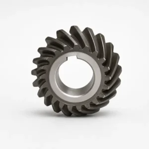
Industrial Bevel Gears – M3 to M20, Up to 1200mm Diameter
-
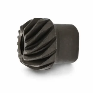
Spiral Bevel Gears – Helical Bevel Gear, Custom OEM Supply
-
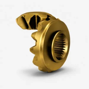
Differential Gears – Open, LSD, Torque Vectoring, Forged PM
-
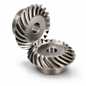
Spiral Bevel Gear – Localized Contact, Min 5 Teeth, M3-M12
-
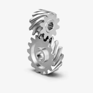
Helical Bevel Gear – Tangential Tooth, Low Noise Bevel Drive
-
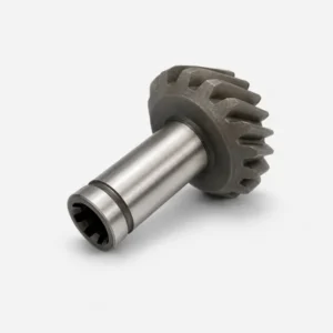
Automotive Bevel Gear – M0.15 to M2.2, AGMA 13 / DIN 5
-
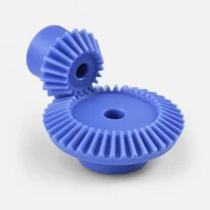
Plastic Bevel Gears – POM PA PEEK, -40°C to 80°C, 1:1–5:1
-
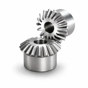
Miter Gears – 1:1 Straight & Spiral, Right-Angle Drive
 English
  Italian
  Korean
  French
  Japanese