
Spiral Miter Gears – 35° Spiral Angle, 1:1 High-Speed Drive
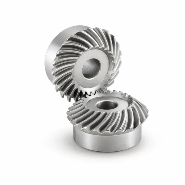
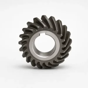
Korea Ever-Power spiral miter gears transmit power between perpendicular shafts at a fixed 1:1 ratio using curved teeth set at a 35° mean spiral angle. The helical tooth form delivers progressively smoother engagement, lower noise, and higher torque capacity than straight miter gears of the same module. Available in carburised alloy steel (SCM415 / 20CrMnTi), stainless steel, and brass; bore with keyway and setscrew as standard. Module 2 through 5 in standard series; other modules per drawing.
Product Overview
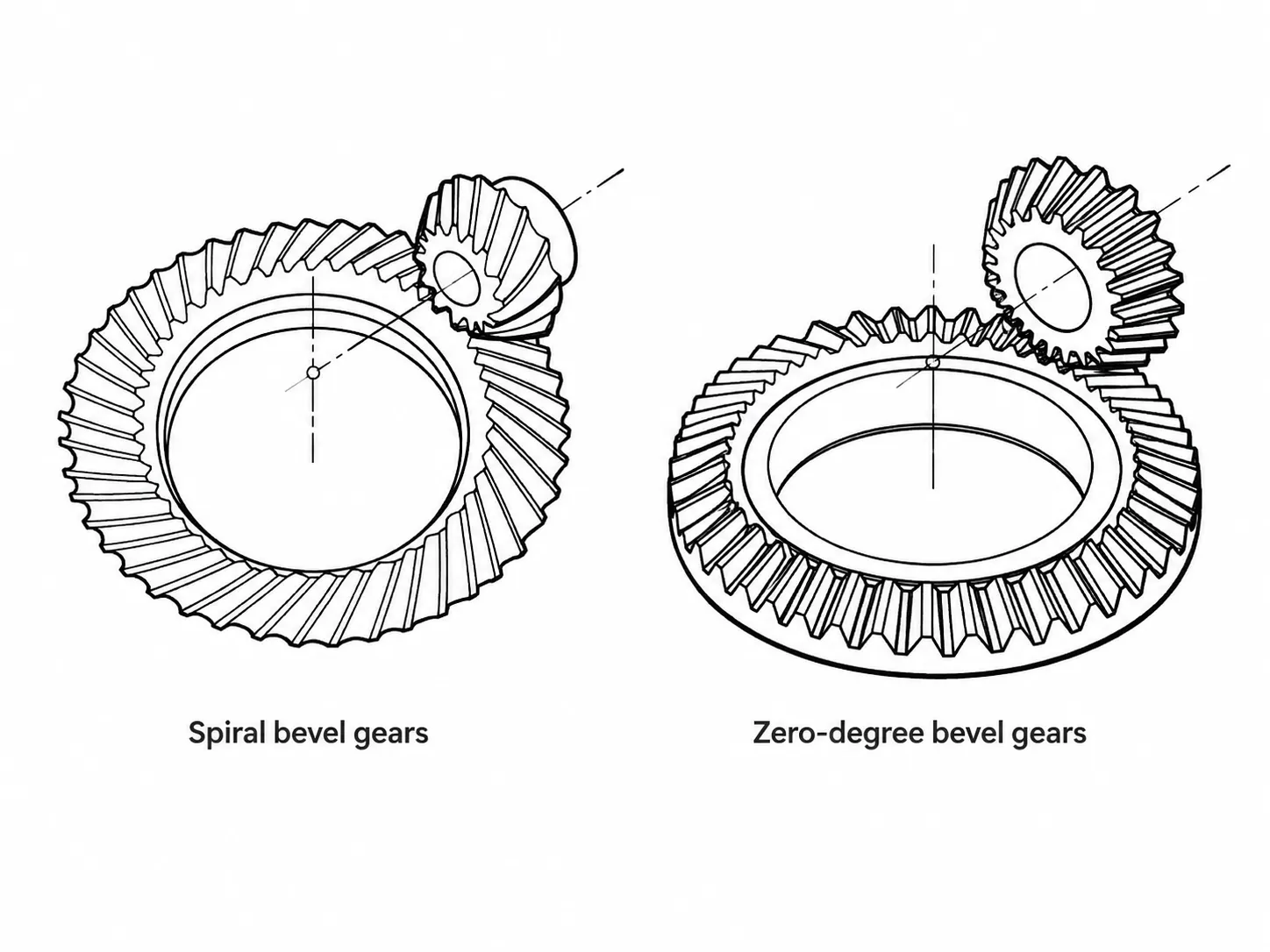
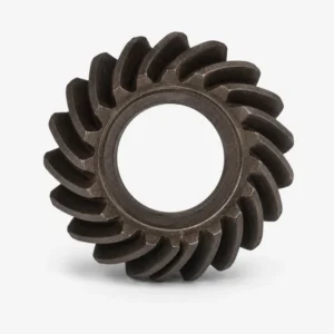
Spiral miter gears are the high-performance variant of the miter gear family. Both members of the pair carry the same tooth count and module — giving a fixed 1:1 speed ratio with a 90° direction change — but the teeth are formed along curved spiral lines across the cone face rather than running straight from toe to heel. This curvature is the source of all the performance advantages that spiral miter gears hold over their straight-cut counterparts: progressively smoother tooth engagement, lower operating noise, higher torque capacity within the same outer diameter, and longer fatigue life at the tooth root.
The standard spiral angle for Korea Ever-Power spiral miter gears is 35° mean spiral angle. This value is the industry-established optimum for right-angle miter drives — it is large enough to ensure multiple teeth are simultaneously in mesh at any instant (raising the contact ratio and smoothing the load transfer), while remaining within the range where the resulting axial thrust load is manageable with standard angular contact or taper roller bearings. A smaller spiral angle provides less contact ratio improvement; a larger spiral angle raises the axial thrust to a level that demands heavier bearings without proportional gain in noise or load capacity.
Korea Ever-Power produces spiral miter gears in a standard series covering module 2 through 5, with carburised alloy steel (SCM415 or equivalent 20CrMnTi) as the principal material grade. The bore is machined with a keyway and setscrew hole as standard, ready for direct fitting to a keyed shaft. Steel, brass, and stainless steel material options cover the full range from high-torque industrial drives to food-contact and corrosion-resistant applications. Modules outside the standard series and non-standard tooth counts are available to customer drawings; all orders include dimensional and hardness documentation.
The 35° Spiral Angle — Engineering Behind the Standard
The spiral angle in a spiral miter gear — measured at the mean cone distance — determines how the tooth length is curved across the face. It has a direct and calculable effect on three engineering quantities that matter in practice:
Face contact ratio
The spiral angle contributes to the face contact ratio — the portion of the total contact ratio that comes from the overlap of successive teeth along the face width. At 35°, the face contact ratio for a typical miter gear module is comfortably above 1.0, meaning more than one tooth pair is always in contact. This is what prevents the instantaneous full-load handoff that produces impact noise in straight miter gears. The load is always shared between two teeth during the transition, so the stress spike at each mesh cycle is eliminated.
Axial thrust magnitude
Axial thrust in a spiral miter gear is proportional to the tangential force multiplied by the tangent of the spiral angle. At 35°, the axial thrust is approximately 70% of the tangential force — significant, but within the range that standard angular contact bearing pairs handle without exotic bearing selection. At a 45° spiral angle the axial thrust equals the tangential force; at 25° it is approximately 47% — less thrust, but contact ratio drops toward the straight-gear regime and the noise advantage diminishes.
Sliding velocity at the tooth flanks
The curvature of the spiral tooth means the contact point moves across the flank during engagement, generating sliding velocity in addition to the rolling velocity that straight bevel gears also have. At 35° the additional sliding is modest relative to a hypoid gear, so standard EP gear oil handles the lubrication requirement without the special hypoid-rated formulation that higher-offset configurations demand.
Technical Specifications
Standard series parameters are listed below. Dimensions and tolerances outside these ranges — including non-standard modules, custom tooth counts, and special bore configurations — are confirmed against customer drawings at the quotation stage before production.
| Parameter | Standard Series / Options |
|---|---|
| Gear Type | Spiral miter gear — right-hand spiral, 90° shaft intersection, 1:1 ratio |
| Module (Standard Series) | Module 2, 3, 4, 5 — other modules per customer drawing |
| Mean Spiral Angle | 35° (industry standard for right-angle miter drives) |
| Pressure Angle | 20° standard |
| Gear Ratio | Fixed 1:1 (equal tooth count and pitch cone angle on both members) |
| Hand of Spiral | Right-hand (standard); left-hand available per drawing |
| Accuracy Grade | JIS 4 (standard); other grades per customer requirement |
| Principal Material | SCM415 (JIS) / 20CrMnTi (GB equivalent) — low-carbon alloy, carburised |
| Material Options | Carbon steel, stainless steel (304 / 316), brass C3604 / C3771 |
| Heat Treatment | Carburising & quenching (standard); through-hardening or normalising per spec |
| Tooth Finish | Cut (non-ground) as standard; lapped pairs available for smoother contact |
| Bore Configuration | Through bore with keyway and setscrew hole (standard fit for keyed shaft) |
| Secondary Operations | All secondary machining possible except on hardened tooth flanks |
| Surface Treatment | Black oxide, phosphating, zinc plating, as-machined (stainless) |
| Certification | ISO 9001:2015; material cert and hardness report with each order |
Note on secondary operations: carburised spiral miter gears can be re-bored, key-seated, or have additional features machined onto the hub or body after heat treatment. The hardened tooth flanks themselves cannot be re-machined without specialist equipment; any modification to tooth geometry after hardening requires re-cutting and re-hardening the complete gear.
Performance Advantages Over Straight Miter Gears
The curved teeth enter and leave mesh gradually, so the load on any single tooth rises and falls smoothly rather than jumping from zero to full load at each mesh cycle. This eliminates the high-frequency impact excitation that gives straight miter gears their characteristic clatter at speed. At pitch-line speeds above 3–4 m/s, the noise difference between straight and spiral miter gears is substantial — spiral gears typically measure 8–12 dB lower under equivalent load and speed conditions.
Because the load is shared across more than one tooth pair at all times, the peak contact stress on any single tooth is lower than for a straight miter gear carrying the same total torque. This allows spiral miter gears to transmit higher torque within the same outer diameter, or to achieve equivalent service life at a smaller outer diameter than the straight alternative. For applications where gear head diameter is constrained by the tool or machine envelope, the spiral tooth form often enables one module step reduction in size.
Lower peak contact stress per tooth directly reduces the rate of pitting accumulation on the tooth flank, which is the dominant failure mode in well-lubricated bevel gear drives. Lower bending stress at the root — again due to load sharing — reduces tooth-root fatigue crack initiation. At equivalent torque, a spiral miter gear in the same material and heat treatment as a straight miter gear will show measurably less tooth surface wear after the same number of load cycles.
Straight miter gears become increasingly noisy and dynamically unstable above approximately 3–5 m/s pitch-line speed due to tooth impact excitation. Spiral miter gears, with their smooth engagement, are well-suited to the higher pitch-line speeds common in power tool angle heads, high-speed machine auxiliary drives, and any application where the motor runs at several thousand rpm without intermediate reduction. The 35° spiral angle specifically is chosen to maximise the speed range relative to the axial thrust penalty.
Carburised SCM415 / 20CrMnTi gives a hard case on the tooth flanks and root — providing contact fatigue resistance and wear resistance — over a tough low-carbon steel core that absorbs shock loads without brittle fracture. This combination is specifically chosen for drive applications where momentary overloads occur: angle grinders momentarily biting into hard material, machine drives reaching hard stops, tool heads reversing under load. A purely through-hardened gear would be more brittle at the core in these scenarios.
The standard bore includes a keyway and setscrew hole machined after heat treatment. This means the gear fits directly onto a standard parallel-key shaft without further machining, reducing the assembly steps between receiving the gear and commissioning the drive. The setscrew provides supplementary retention against axial movement on the shaft — particularly useful in drives where axial thrust from the spiral tooth geometry could otherwise walk the gear along the keyway.
Managing Axial Thrust in Spiral Miter Gear Drives
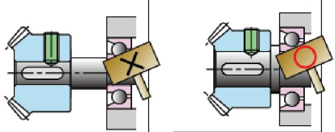
The axial thrust generated by a spiral miter gear is the most important design consideration that differentiates spiral from straight miter gear installations. It is not a defect or a disadvantage that can be eliminated — it is a consequence of the tooth geometry that must be accounted for in the bearing and housing design. Understanding the direction and magnitude of the thrust allows the engineer to select the correct bearing type and arrangement.
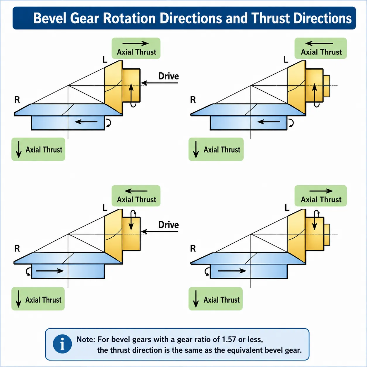
Thrust direction depends on two factors: the hand of spiral and the direction of rotation. For a right-hand spiral miter gear — the standard Korea Ever-Power configuration — rotating clockwise when viewed from the large end of the cone, the axial thrust on the gear pushes toward the large end (away from the apex). If the same gear rotates anticlockwise, the thrust reverses and pushes toward the small end. Since both gears in a right-angle miter set carry the same hand of spiral convention, the thrust on each shaft points in a geometrically predictable direction that can be read from the thrust direction diagram supplied with the gear set.
Bearing selection for unidirectional drives: angular contact ball bearings in pairs (back-to-back or face-to-face arrangement), or taper roller bearings with pre-load shimming, are standard choices. Both handle combined radial and axial loads at the speeds typical of power tool and machine auxiliary drives. Deep-groove ball bearings with adequate axial load capacity are also used in lighter-duty spiral miter drives where cost is a priority. For reversing drives — where the thrust changes direction with each reversal — the bearing arrangement must carry axial thrust in both directions simultaneously; back-to-back angular contact pairs are the most reliable solution in this case.
Practical rule: For a right-hand spiral miter gear driving clockwise, size the outboard bearing (away from the gear) to carry the thrust load; the gear pushes toward the large end and the outboard bearing is the reaction point. For reversing drives, use a back-to-back angular contact pair with pre-load on both bearings so neither bearing unloads during reversal. Korea Ever-Power includes a thrust direction diagram and an indicative axial force calculation with every spiral miter gear quotation on request.
Applications
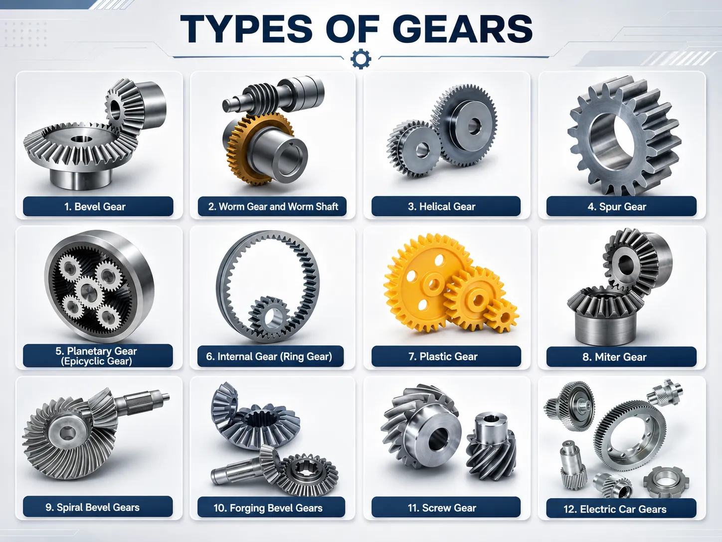
Spiral miter gears occupy the performance tier of the miter gear family — where speed is above the practical limit for straight-cut gears, torque density is a design constraint, or noise in the final product is regulated. The applications below represent the primary sectors where Korea Ever-Power spiral miter gears are deployed.
🔧 Angle Grinders & Power Tool Heads
The gearhead of an angle grinder spins the disc at high speed using a spiral miter gear pair that turns the motor output through 90°. The spiral angle is essential here — a straight-cut gear at the same speed would generate noise and vibration that makes the tool uncomfortable to hold and accelerates bearing wear. Carburised alloy steel is the standard material for the high continuous torque and momentary overloads typical in grinding and cutting.
🌿 Lawn Trimmers & Garden Equipment
A brush cutter or string trimmer routes the engine output shaft to the cutting head through a 90° angle at the bottom of the drive tube. Spiral miter gears handle the continuous high speed of a two-stroke engine while keeping the gearhead compact enough to fit inside the drive tube housing. The gradual tooth engagement also smooths out the vibration that would otherwise travel up the drive shaft to the operator's hands.
⚙ Machine Tool Angle Heads
Right-angle milling heads and drill angle adaptors for CNC machining centres use spiral miter gear pairs to redirect spindle torque at 90° while preserving the spindle speed set by the machine control. The 1:1 ratio means feeds and speeds calculated for the main spindle apply directly at the tool tip without recalculation. JIS 4 accuracy grade ensures low transmission error at machining speeds, which is necessary for dimensional accuracy in the workpiece.
📚 Printing & Packaging Drives
High-speed printing machines and packaging line drives use spiral miter gears where a direction change is needed between a main drive shaft and a cross-running roller or knife shaft. At the pitch-line speeds of modern printing presses, smooth tooth engagement is not just a comfort feature — any transmission error shows up as a repeating pattern defect in the printed output. Spiral miter gears provide the consistent angular velocity transmission that precision print registration demands.
📊 Instrumentation & Test Equipment
Test rigs and instrumentation that must transmit rotation at precise 1:1 velocity with minimal vibration use spiral miter gear pairs in stainless steel or brass. The low noise floor of a spiral miter pair reduces mechanical noise contamination in vibration measurement equipment, and the stainless or brass materials avoid corrosion in temperature and humidity-controlled laboratory environments.
🏭 Industrial Conveyor & Feed Drives
Conveyor cross-drives, side-discharge mechanisms, and material feed systems where the main drive runs perpendicular to the conveyor direction use spiral miter gears to make the turn without a belt or chain stage. The direct gear drive eliminates belt slip and the maintenance of chain lubrication, and the spiral tooth form ensures quiet continuous operation in production environments where noise levels are regulated.
Material Detail — SCM415 / 20CrMnTi Carburised Steel
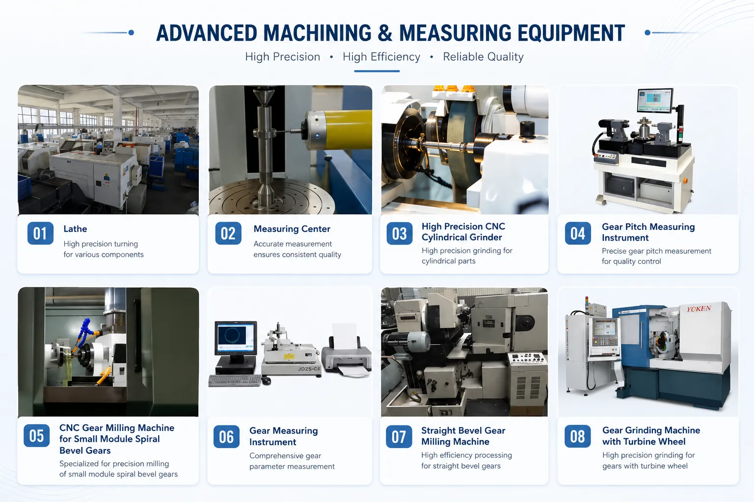
SCM415 (JIS designation) and its Chinese GB-standard equivalent 20CrMnTi are both low-carbon chromium-molybdenum alloy steels with approximately 0.13–0.18% carbon content. The low carbon level is intentional — it keeps the core of the gear ductile and tough after quenching, while the carburising process adds a carbon-enriched case to the tooth flanks and root that can be hardened to high surface hardness.
The carburising cycle diffuses carbon into the surface to a controlled depth. The gear is then quenched to harden the case while the low-carbon core remains in a tough, non-brittle condition. This case-and-core structure is specifically engineered for gear applications: the hard case resists contact fatigue (pitting) and abrasive wear at the tooth flank; the tough core resists bending fatigue at the root and absorbs shock without brittle fracture. Through-hardened steels of equivalent surface hardness would have a brittle core that fails catastrophically under sudden overload — the case-hardened structure fails progressively, giving warning before complete tooth loss.
Secondary operations — re-boring, counter-boring, adding tapped holes, modifying the hub face — are all possible on carburised spiral miter gears after hardening, because the bulk of the gear body remains machinable. Only the hardened tooth flanks resist cutting and require specialist grinding equipment if modification is needed. This is why the specification note from the original product data reads: "Secondary operations are possible except for the teeth."
| Material | Best For | Relative Load Rating | Note |
|---|---|---|---|
| SCM415 / 20CrMnTi (carburised) | High-speed, high-torque drives; power tools; machine heads | Highest | Standard production grade |
| Carbon steel (through-hardened) | Moderate load, intermittent duty, shock tolerance | High | Per customer drawing |
| Stainless steel 304 / 316 | Food, marine, pharmaceutical, lab environments | Moderate | Lower load than alloy steel at same module |
| Brass C3604 / C3771 | Instruments, lightly loaded drives, corrosion-sensitive environments | Low | Runs quietly; no sparking |
Frequently Asked Questions
Can a spiral miter gear mesh with a straight miter gear?
No. Spiral and straight miter gears of the same module and tooth count cannot mesh together. The tooth geometry differs fundamentally — a spiral tooth has curvature across the face that a straight tooth does not, and the contact conditions, pressure angle projection, and lead angle are all different between the two forms. Attempting to mesh them would produce edge contact, high stress concentrations, and rapid damage to both gears. Always replace spiral miter gears with spiral miter gears of the same spiral angle and hand, and straight miter gears with straight miter gears.
What does JIS 4 accuracy grade mean in practice?
JIS 4 is a gear accuracy class defined in the Japanese Industrial Standard JIS B 1704. It specifies tolerances on tooth spacing error, pitch variation, runout, and tooth profile form. JIS 4 is a production-grade accuracy suitable for most industrial and power tool applications — it delivers low transmission error at the speeds common in angle grinder and machine auxiliary drive applications without requiring the tighter tolerances (and associated cost) of precision instrument or high-speed printing gear grades. For comparison, JIS 4 is broadly equivalent to AGMA Quality 8 and DIN quality class 7 in transmission error terms. If your application requires tighter control — for example, a precision coordinate measurement machine drive — please specify the required accuracy class at the enquiry stage and we will confirm achievability.
Why are spiral miter gears always supplied as a right-hand spiral as standard?
For a 1:1 miter pair, both gears in the set are always opposite hands — if the driving gear is right-hand, the driven gear is left-hand. The convention of calling the set "right-hand" refers to the driving member (typically the pinion in a non-equal set, but either member in a 1:1 miter pair). Korea Ever-Power supplies the standard pair with the driving gear as right-hand spiral. If your housing, bearing arrangement, or rotation direction requires a left-hand driving gear, specify this at the quotation stage — it is a straightforward change to the cutting setup and does not affect price or lead time for standard module sizes.
How should I lubricate a spiral miter gear drive?
For enclosed splash-lubricated angle head gearboxes, an ISO VG 100 to VG 150 gear oil with EP additive is appropriate at the pitch-line speeds typical of power tool drives (above 10 m/s). At lower speeds — machine auxiliary drives, conveyor heads — ISO VG 220 is the more common choice. Spiral miter gears do not require the special hypoid-rated lubricant that offset hypoid gears need, because the sliding velocity at the tooth flank is significantly lower than in a hypoid set at equivalent pitch-line speed. For grease-lubricated sealed units, NLGI Grade 2 lithium-complex grease with EP additive provides adequate film at the tooth flanks in most sealed angle head applications. The grease cavity should be filled to no more than one-third of the free volume to avoid churning heat buildup.
Can I re-bore a spiral miter gear to a larger bore diameter after receiving it?
Yes, for carburised SCM415 / 20CrMnTi gears — the bore and hub area are in the as-quenched low-carbon steel core, which remains machinable. The hardened tooth flanks cannot be re-machined without specialist grinding. The practical limit on bore enlargement is determined by the minimum wall thickness between the enlarged bore and the root of the teeth — reducing this below approximately 1.5 to 2 times the module puts the root in tension during operation and risks cracking. Our engineering team can confirm the maximum bore for your specific module and tooth count before you commit to a bore size.
What is the difference between a cut (non-ground) and a lapped spiral miter gear?
A cut (non-ground) spiral miter gear has tooth flanks in the as-cut, as-hardened condition — the surface roughness and profile accuracy are as left by the gear cutting machine and the heat treatment distortion. This is adequate for most industrial drives at JIS 4 accuracy. A lapped pair is run together with a mild abrasive compound to remove asperities and optimise the contact pattern between the two mating surfaces, reducing surface roughness and improving the contact ratio consistency across the face width. Lapping also produces a matched pair — the contact pattern belongs to that specific pairing and should not be mixed with other individual gears. Lapped pairs are worth specifying for drives requiring low noise at high speed or for applications where the running-in period must be minimised. Enquire with our team if you need a lapped spiral miter pair and we will confirm lead time and cost.
Customer Reviews
"We manufacture angle grinder gearheads for an industrial tool brand. The SCM415 carburised spiral miter pairs from Ever-Power have consistently passed our 500-hour continuous torque test. Noise level in the assembled tool is within spec across every batch received over the past 18 months. The ready-fit bore with keyway saves us one machining step in assembly."
Jang Hyeon-woo | Manufacturing Engineer, Incheon Power Tool Manufacturing · Q1 2026
"We replaced worn spiral miter gears in a high-speed printing machine cross-drive. The previous set was sourced from a Japanese supplier with a 12-week lead time. Ever-Power matched the module and spiral angle from the worn sample, supplied in module 3 SCM415, and delivered in under four weeks. Register accuracy in the press returned to the original specification after fitting."
Nam Gi-tae | Press Maintenance Manager, Gyeonggi Commercial Printing · Q3 2025
"We use module 2 stainless steel spiral miter pairs in a laboratory test rig for vibration measurement. The noise floor contribution from the gear drive is below our measurement threshold — we cannot distinguish the gear noise from the baseline. The stainless material has shown no corrosion in the humidity-controlled test environment after two years of intermittent use."
Son Yeon-soo | Research Engineer, Seoul Dynamics Laboratory · Q2 2025
"We design brushcutter angle drives for OEM sale. The spiral miter gear pair is the highest-wear component in the drive, so we evaluate suppliers closely. Ever-Power's carburised SCM415 pairs have outlasted the previous steel supplier's gears in our 100-hour accelerated wear test. The contact pattern photograph they include with each batch confirms consistent lapping across deliveries."
Hwang Min-jun | Product Development Lead, Daejeon Outdoor Power Systems · Q4 2025
"We specified module 4 brass spiral miter pairs for an instrument drive in an atmospheric testing chamber — the environment precludes steel due to aggressive salt-fog conditions. Ever-Power machined the bore and keyway to our exact drawing, including a non-standard bore diameter that required a custom broach. The gears arrived within the committed lead time with material certification for the brass grade."
Park Ji-hyun | Test Equipment Engineer, Busan Aerospace Test Systems · Q1 2026
Request a Quotation for Spiral Miter Gears
Send us your module, bore diameter, material, and hand of spiral — or share a drawing or worn sample gear. Standard series module 2 to 5 in SCM415 carburised steel, stainless, or brass. Our engineering team returns a price and lead time within two working days.
Additional information
| Editor |
|---|
Related products
-
Spiral Bevel Gear – Localized Contact, Min 5 Teeth, M3-M12
-
Bevel Gears European Standard – DIN Type A & B, 1:1 to 1:4
-
Differential Gears – Open, LSD, Torque Vectoring, Forged PM
-
Plastic Bevel Gears – POM PA PEEK, -40°C to 80°C, 1:1–5:1
-
Miter Gears – 1:1 Straight & Spiral, Right-Angle Drive
-
Industrial Bevel Gears – M3 to M20, Up to 1200mm Diameter
-
Precision Bevel Gear – M0.15 to M2.2, AGMA 13, 5 HT Routes
-
Automotive Bevel Gear – M0.15 to M2.2, AGMA 13 / DIN 5
 English
  Italian
  Korean
  French
  Japanese