
Zero-Degree Spiral Bevel Gear – Zerol, No Axial Thrust
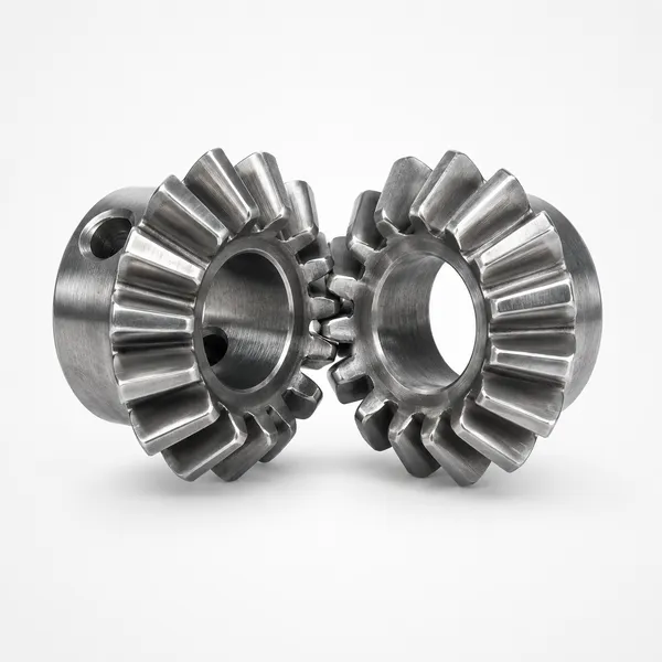
Korea Ever-Power zero-degree spiral bevel gears (Zerol bevel gears) have a midpoint spiral angle of exactly zero degrees — the curved teeth follow the same angular direction as a straight bevel gear, but are machined on spiral bevel gear equipment using circular-arc cutting, producing localised point contact on the tooth surface. The result is a gear that generates the same axial bearing load as a straight bevel gear while gaining the localised contact tolerance advantage of the spiral form. Both types are directly interchangeable in the same housing and bearing arrangement. Modules M3 to M12, ISO / DIN / ANSI / JIS / BS standards, multiple materials and surface treatments.
Product Overview
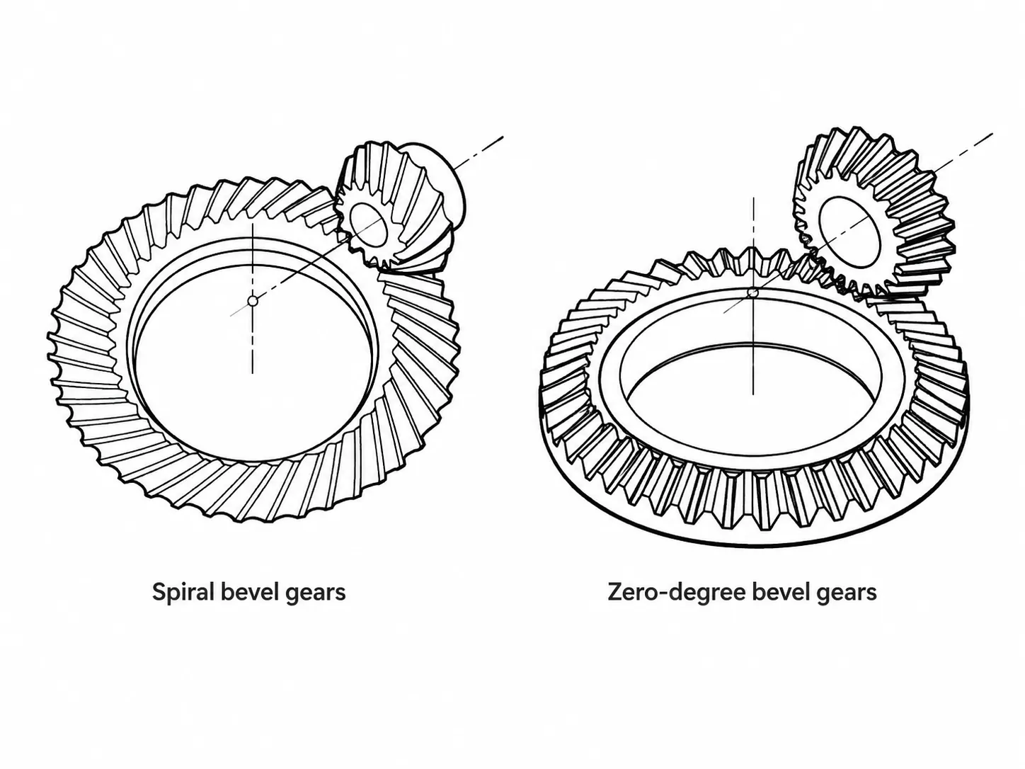
A zero-degree spiral bevel gear — often called a Zerol bevel gear after the Gleason Works trade designation — is defined by one precise geometric condition: the mean spiral angle at the midpoint of the tooth face width is exactly zero degrees. This means the curved teeth, when measured at the midpoint of the face, follow the same angular direction as the tooth lines of a straight bevel gear. The curvature is present along the tooth length, but the net angle at mid-face is zero. The gear is machined on standard spiral bevel gear cutting equipment using a circular-arc cutter, not on straight bevel gear machines.
This specific geometry creates a gear that sits in an unusual position in the bevel gear family — it shares one critical characteristic with each of the two adjacent gear types, but without inheriting the drawbacks of either. From the straight bevel gear it inherits zero net axial thrust: because the midpoint spiral angle is zero, the axial thrust component that characterises a non-zero spiral bevel gear is absent at the design load point. This means the zero-degree spiral bevel gear generates exactly the same bearing load as a straight bevel gear in the same application, and the two are directly interchangeable in the same housing, on the same shafts, with the same bearing arrangement — no bearing redesign required.
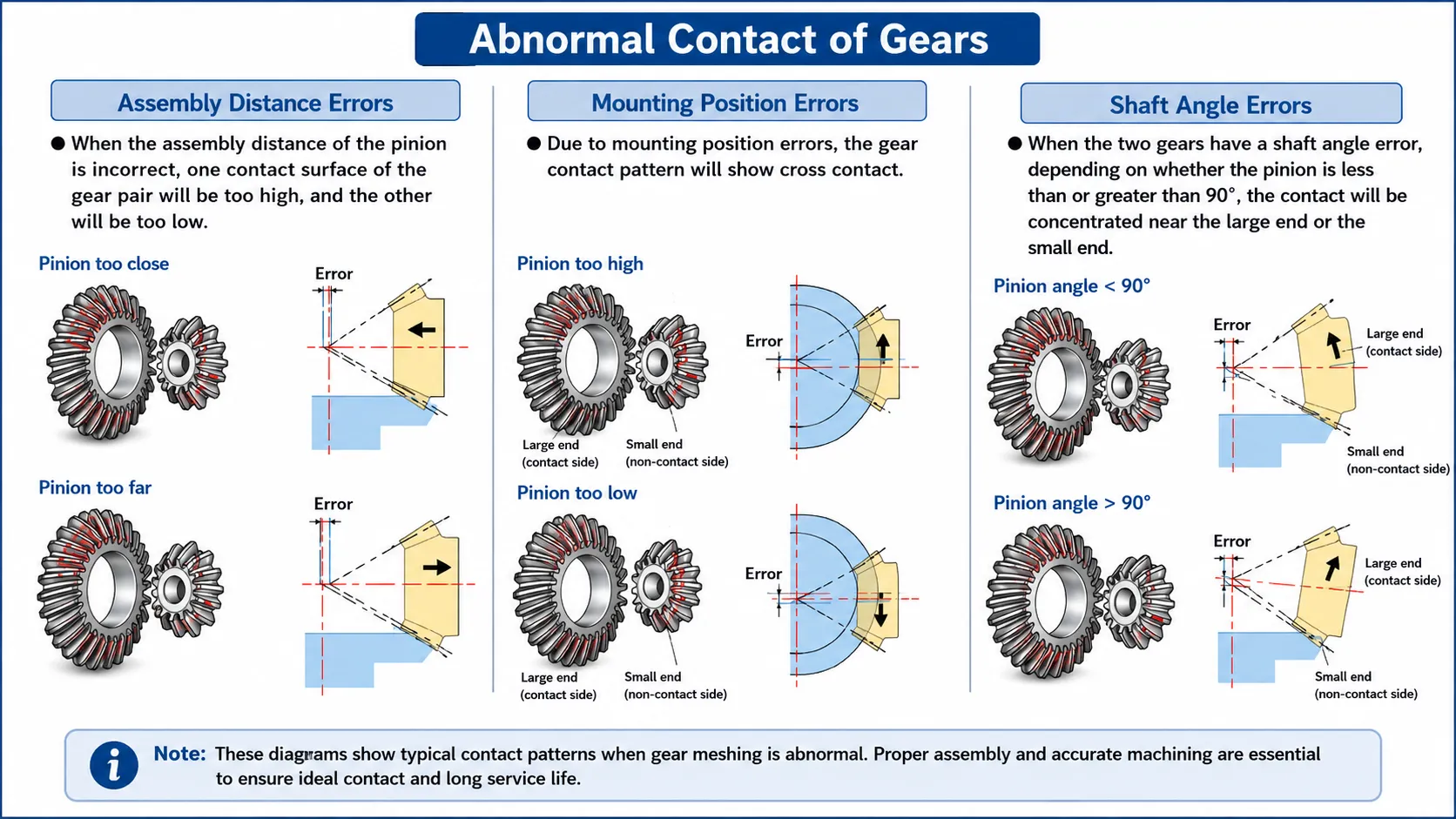
From the spiral bevel gear it inherits localised point contact on the tooth surface. Because it is machined using circular-arc spiral bevel equipment, the tooth surface carries the same localised contact characteristic as an ordinary spiral bevel gear — the contact zone is a defined area rather than a full line, making the gear tolerant of small deviations in mounting distance and shaft alignment. This is precisely where the zero-degree spiral bevel gear outperforms the straight bevel gear it can replace: the localised contact means the replacement gear maintains acceptable load distribution even when the housing geometry is slightly imperfect, whereas a straight bevel gear in the same housing with the same deviation would shift to edge contact and higher stress.
The Defining Geometry — Zero Mean Spiral Angle Explained
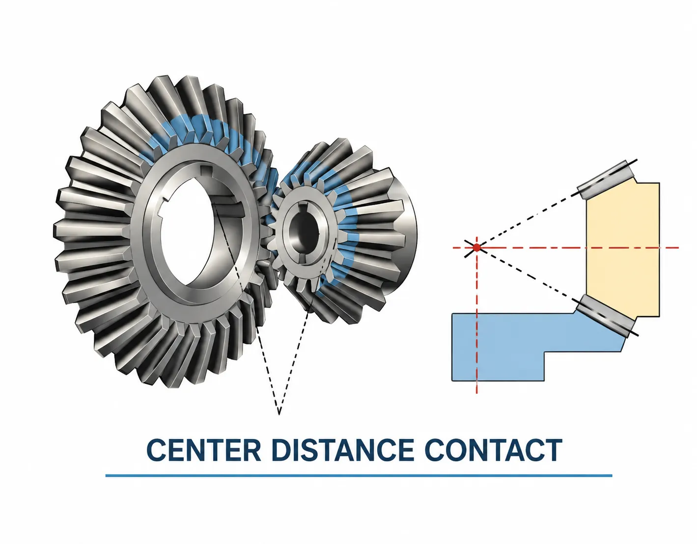
The term "mean spiral angle" refers to the spiral angle measured at the midpoint of the tooth face width — not at the heel (large end) or the toe (small end), but at the mid-face. In a standard spiral bevel gear this angle is typically 25° to 40°. In a zero-degree spiral bevel gear it is, by definition, exactly 0°.
Despite the zero mean spiral angle, the tooth is not straight — it has curvature along the face width because it is cut with a circular-arc cutter. The cutter sweeps an arc across the tooth face, and this arc means the spiral angle at the toe is a positive value and the spiral angle at the heel is a negative value of equal magnitude. These two non-zero values cancel each other at the midpoint, giving a net mean spiral angle of zero.
Why the axial thrust is zero
Axial thrust in a bevel gear arises from the tangential force component resolved along the gear axis by the spiral angle. With a mean spiral angle of zero, this resolution produces no net axial force at the design load condition. The thrust contributions from the toe half of the tooth (positive spiral angle) and the heel half (negative spiral angle) cancel. This is not an approximation — it is a precise consequence of the geometry when the mean spiral angle is exactly zero.
Why localised contact is still present
Even with zero mean spiral angle, the curvature of the tooth surface created by the circular-arc cutter produces a convex tooth form in the lengthwise direction. When two convex surfaces meet under load, the contact is localised — initially at a point that spreads to an elliptical area as load increases. This is fundamentally different from the theoretical line contact of a straight bevel gear, and it is this localised contact that gives the zero-degree spiral bevel gear its tolerance to mounting deviation.
Three-Way Comparison — Straight, Zero-Degree Spiral, and Spiral Bevel Gears
The zero-degree spiral bevel gear's engineering position is best understood by placing it between the straight bevel gear and the standard spiral bevel gear in a direct comparison. The table below covers the criteria that matter most when selecting between these three forms.
| Criterion | Straight Bevel Gear | Zero-Degree Spiral Bevel | Standard Spiral Bevel |
|---|---|---|---|
| Mean spiral angle | 0° (by definition, straight tooth) | 0° at midpoint; tooth is curved | 25° – 40° typically |
| Tooth form | Straight (no curvature) | Curved (circular-arc) | Curved spiral |
| Axial thrust | None | None — same as straight bevel | Present; direction depends on hand |
| Bearing load | Standard radial + separating | Identical to straight bevel | Additional axial component |
| Contact type | Theoretical line → edge under deviation | Localised point — tolerant of deviation | Localised — tolerant of deviation |
| Interchangeable with straight bevel? | — | Yes — same housing and bearing | No — bearing must handle axial load |
| Contact ratio | Lowest | Slightly higher than straight | Highest |
| Noise at speed | Higher above ~3 m/s | Lower than straight — curved engagement | Lowest |
| Cutting machine | Straight bevel machines | Spiral bevel machines (Gleason etc.) | Spiral bevel machines |
| Primary use case | Low speed, simple drives | Drop-in upgrade for straight bevel — better contact, same bearings | High speed, high torque, new designs |
The interchangeability with straight bevel gears is the most practically important property in the table above. When an engineer wants to improve the performance of an existing straight bevel drive — reducing noise, improving resistance to housing deviation, extending tooth life — but cannot change the bearing design or housing geometry, the zero-degree spiral bevel gear is the only form that achieves this improvement while fitting directly into the existing arrangement.
Technical Specifications
All specific values are confirmed against your drawing or application data at the quotation stage. For replacement of existing straight bevel gears, submit the worn gear or the original drawing and specify that the replacement should be in zero-degree spiral bevel form.
| Parameter | Standard Range / Options |
|---|---|
| Gear Type | Zero-degree spiral bevel gear (Zerol bevel gear) — curved circular-arc tooth, zero mean spiral angle |
| Mean Spiral Angle | 0° at midpoint of face width (defining characteristic) |
| Axial Thrust | None — same bearing load as equivalent straight bevel gear |
| Contact Type | Localised point / elliptical area — tolerant of mounting deviation |
| Interchangeability | Directly interchangeable with straight bevel gear of same module and ratio in same housing |
| Module (Standard) | M3, M4, M5, M8, M12; other modules per customer drawing |
| Pressure Angle | 20° standard; other angles per drawing |
| Shaft Intersection Angle | 90° standard; other angles per drawing |
| Precision Grade | DIN 6, DIN 7, DIN 8, DIN 9 |
| Manufacturing Standard | ISO, DIN, ANSI, JIS, BS, non-standard; customer drawings accepted |
| Tolerance | 0.001 mm – 0.01 mm – 0.1 mm (grade-dependent) |
| Tooth Treatment | Hardened, milled, or ground; lapped pairs for matched sets |
| Material — Ferrous | C45 carbon steel, alloy steel (40Cr, 42CrMo, 20CrMnTi), stainless steel (304, 316) |
| Material — Non-Ferrous | Brass, copper, aluminium alloy |
| Material — Non-Metallic | POM (acetal), engineering resins (light load) |
| Surface Treatment | Zinc-plated, nickel-plated, passivation, black oxide, phosphating, anodisation, Dacromet, powder coating, electrophoresis |
| QA Documentation | Chemical composition, mechanical performance, UT (optional), heat treatment curve, dimensional inspection |
When and Why to Upgrade from a Straight Bevel Gear
The most common reason engineers specify a zero-degree spiral bevel gear for an existing straight bevel drive is one of the following recurring problems. In each case, the upgrade requires no changes to the bearing arrangement, shaft dimensions, or housing — the new gear fits exactly where the old one came out.
Recurring edge contact and early pitting
A straight bevel gear in a housing with imperfect bore alignment or a shaft that deflects more than expected will shift its contact zone toward one edge, concentrating stress and initiating pitting far earlier than the design life. Replacing with a zero-degree spiral bevel gear of identical module and tooth count introduces localised contact — the contact zone remains on the tooth face despite the same mounting deviation, and pitting life recovers without any change to the gearbox structure.
Gear noise above acceptable limits
Straight bevel gears become progressively noisier above approximately 3 m/s pitch-line speed due to the impact excitation at each full-face tooth engagement. A zero-degree spiral bevel replacement introduces curved tooth engagement — the contact begins at one end of the tooth and progresses across the face — which reduces the impact excitation and lowers the gear noise without requiring a spiral bevel gear with its associated axial thrust and bearing redesign.
Short service life without clear cause
When a straight bevel gear pair consistently fails before its calculated design life and no obvious overload or lubrication failure is found, the root cause is often a housing or shaft tolerance stack that puts the contact zone near the tooth edge during service — not visible to inspection without a loaded contact test. The zero-degree spiral bevel replacement provides contact life margin against these hidden deviations, frequently doubling or tripling gear life in drives where the housing geometry is difficult to control tightly.
Key Advantages
The mean spiral angle of zero produces no axial bearing load at the design torque. Existing bearing arrangements sized for a straight bevel gear handle the zero-degree spiral bevel replacement without modification — no change to bearing type, pre-load, or housing thrust face.
A zero-degree spiral bevel gear and a straight bevel gear of the same module and ratio are interchangeable in the same housing on the same shafts with the same bearing arrangement. The outer envelope of the gear body is identical; only the tooth form differs. This makes the zero-degree form a drop-in performance upgrade with no associated redesign cost.
The circular-arc tooth curvature creates localised point contact that expands to an elliptical area under load. This contact form is tolerant of small housing bore misalignment, shaft deflection, and bearing clearance variation — all of which push a straight bevel gear toward edge contact and early pitting.
The curved tooth introduces progressive contact — the load transitions across the face rather than landing all at once — which reduces the tooth mesh impact excitation and lowers gear noise at moderate to higher pitch-line speeds compared with the straight bevel gear it replaces.
Being produced on the same Gleason-type cutting machines as spiral bevel gears, the zero-degree form benefits from the same precision and process control. The resulting tooth accuracy and surface finish are significantly better than typical straight bevel gears cut on older generating machines, contributing to the noise and life improvement even before the contact zone geometry is considered.
Because there is no net axial thrust, reversal of rotation direction does not change the bearing load direction. This is an advantage in reversing drives — hoists, indexing mechanisms, back-and-forth conveyors — where a standard spiral bevel gear would alternately push and pull the bearing in the axial direction, demanding a stiffer bearing pre-load arrangement.
Applications
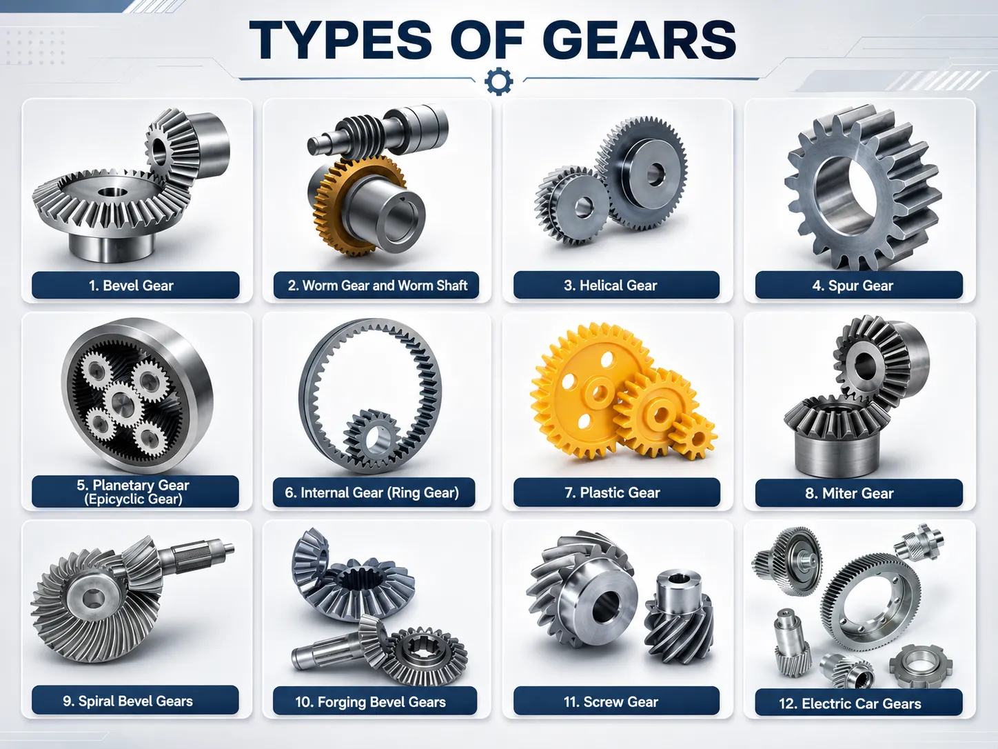
Zero-degree spiral bevel gears are most commonly specified in two contexts: as a performance upgrade replacement for worn straight bevel gears in existing drives, and in new designs where the zero-thrust characteristic is a specific requirement alongside improved contact tolerance. The application sectors below reflect both usage patterns.
Machine Tools
Machine tool headstocks, dividing heads, and indexing tables that originally used straight bevel gears often develop noise or early wear when the spindle deflects under cutting load. Replacing with zero-degree spiral bevel gears in the same housings reduces both noise and sensitivity to spindle deflection without requiring bearing changes — an important constraint in machine tool rebuilding where changing the bearing design affects the entire headstock assembly.
Automatic Controlling Machines
Servo-driven positioning axes and cam-controlled machines use right-angle drives where bidirectional operation is common. The absence of axial thrust in either rotation direction simplifies bearing selection and eliminates the need to pre-load the axial bearing arrangement for reversal loads — an advantage over both straight bevel gears (which need pre-load for noise at speed) and spiral bevel gears (which generate thrust reversal on rotation change).
Semi-Conductor Equipment
Wafer handling robots and precision positioning stages in semi-conductor fabrication require smooth, low-vibration angular transmission. The zero-degree spiral bevel form in stainless steel or aluminium provides lower noise than a straight bevel alternative in the same compact housing, while zero thrust load simplifies the actuator shaft bearing design — important in systems where bearing pre-load is already constrained by thermal expansion requirements.
Medical Equipment
Medical imaging gantry drives, surgical robotic wrists, and hospital bed adjustment mechanisms use bevel gears in compact housings where bearing redesign is not practical. The zero-degree spiral bevel gear provides the noise reduction and localised contact tolerance needed for smooth, quiet operation in patient-facing equipment, within the same housing envelope as the original straight bevel design.
Solar Energy Equipment
Solar tracker drives frequently reverse direction to follow the sun through the day and return to the start position overnight. The zero-thrust characteristic of the zero-degree spiral bevel form simplifies the actuator gear drive design compared with a spiral bevel stage that would generate alternating axial loads on the screw or linear actuator bearing during reversal.
Aviation & High-Speed Rail
Aircraft auxiliary gearboxes and rail bogie drives that originally used straight bevel gears benefit from Zerol replacements when noise or early pitting is reported in service without the option to redesign the bearing arrangement. The maintenance documentation package — material cert, UT report, heat treatment curve, dimensional inspection — meets the traceability requirements of aviation and rail service organisations.
Quality Assurance & Testing
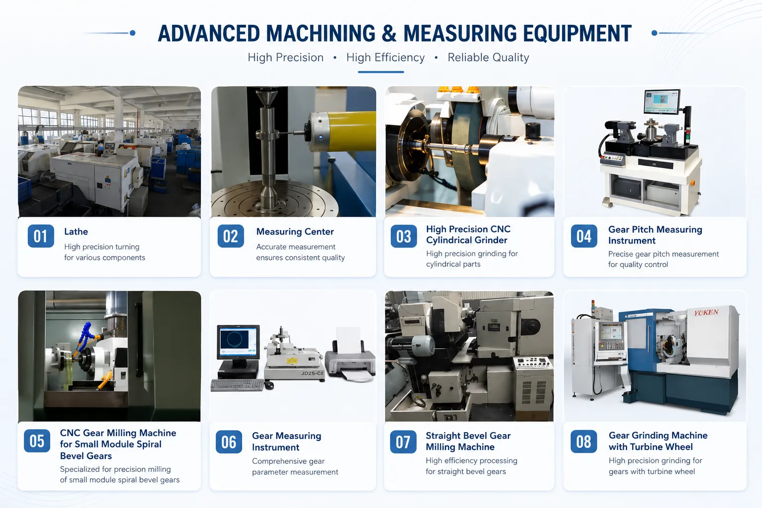
Korea Ever-Power applies its standard quality assurance sequence to all zero-degree spiral bevel gear production. The following documentation ships with every order:
- Chemical composition report — mill certificate and independent spectral analysis confirming steel grade before any cutting begins.
- Mechanical performance report — tensile strength, yield strength, elongation, and impact toughness from test pieces in the same heat as production parts.
- Ultrasonic test (UT) — 100% UT per EN 10228-3, SA388, or customer standard, available as a selectable option for safety-critical and aviation/rail applications. Performed on the blank before gear cutting.
- Heat treatment report — original time-temperature curve from the furnace run, retained per batch, confirming the hardening cycle met specification.
- Dimensional inspection report — CMM verification of pitch cone angle, mean spiral angle (confirmed at zero), bore, OD, face width, and tooth spacing error against drawing tolerances.
- Roll-test contact pattern photograph — contact zone position verified on the roll-test bench and photographed before shipment, giving the installer a reference for assembly contact check.
Frequently Asked Questions
If the zero-degree spiral bevel gear has no axial thrust, why is it cut on spiral bevel machines rather than straight bevel machines?
The zero mean spiral angle describes the net angular position of the tooth at mid-face — it does not mean the tooth is geometrically straight. The tooth is curved in the lengthwise direction because it is generated by a rotating circular-arc cutter that sweeps across the face, leaving a curved profile. Straight bevel gear cutting machines produce a genuinely straight tooth with no curvature along the face. The Gleason-type spiral bevel cutting machine is the equipment that can produce a curved tooth with a controllable spiral angle, including the special case where that angle is zero at the midpoint. The curvature is what creates the localised contact; without the spiral bevel machine, the curved tooth cannot be produced. This is why the zero-degree spiral bevel gear, despite its zero axial thrust, is considered part of the spiral bevel family and is cut on spiral bevel equipment.
Can I replace a worn straight bevel gear pair with zero-degree spiral bevel gears without changing the bearings?
Yes — this is the primary use case for the zero-degree spiral bevel gear. Because the bearing load is identical to that of a straight bevel gear of the same module and ratio, the existing bearings, housings, and shim arrangements remain correct for the replacement gear. The only change is the tooth form. In practice this means you need to specify the same module, tooth count, pitch cone angle, bore, and hub dimensions as the original straight bevel gear, with the instruction to produce in zero-degree spiral bevel form. Korea Ever-Power's engineering team confirms this compatibility at the quotation stage and notes any dimension that must be verified against the original gear before production.
Is the zero-degree spiral bevel gear better than a straight bevel gear in all situations?
No — in applications where pitch-line speed is very low, load is very light, and housing geometry is tightly controlled, the performance difference between straight and zero-degree spiral bevel gears is negligible in practice and the simpler straight bevel gear may be the more economical choice. The zero-degree form is genuinely advantageous when one or more of the following apply: pitch-line speed is above approximately 3 m/s, housing bore accuracy or shaft deflection is difficult to control tightly, noise at moderate speed is a concern, or the drive reverses and the designer wants to avoid alternating axial thrust loads on the bearings. For most drives above light duty, the zero-degree spiral bevel gear is the better long-term choice within the same bearing and housing design.
Does a zero-degree spiral bevel gear need to be replaced in a matched pair like a standard spiral bevel gear?
Yes. Zero-degree spiral bevel gears are lapped in pairs during manufacture to optimise the localised contact zone on both members simultaneously. The contact pattern belongs to the specific pairing of ring gear and pinion produced together. Fitting a new pinion to a worn ring gear of a lapped Zerol pair will produce a different contact zone than the optimised one, and may result in noise and accelerated wear on the new part. Replace zero-degree spiral bevel gear sets as complete matched pairs, in the same way as standard spiral bevel gear sets.
What lubricant should be used with zero-degree spiral bevel gears?
Standard EP gear oil — the same grade used with straight bevel gears in the same housing — is correct for zero-degree spiral bevel gears. Unlike hypoid gears, the Zerol form does not generate the high sliding velocity at the tooth flank that hypoid gears produce, so no special hypoid-rated lubricant is needed. If the original gearbox ran on ISO VG 220 EP mineral oil, the zero-degree spiral bevel replacement runs on the same oil. This is another aspect of the direct interchangeability with straight bevel gears — lubricant specification does not change.
How do I specify a zero-degree spiral bevel gear replacement for an existing straight bevel gear?
The simplest approach is to send us the worn straight bevel gear (ideally both members of the pair) along with the original drawing if available. State that you want the replacement produced in zero-degree spiral bevel form. Our engineering team confirms the module, tooth count, pitch cone angle, bore, hub length, and face width from your sample, and produces the Zerol version to these same external dimensions with a zero mean spiral angle and localised contact. If you have only the drawing and not the worn gear, provide the module, tooth count, pitch cone angle, bore, hub diameter, hub length, and face width, and indicate whether the gear is for a 90° intersection or another angle. Contact our team with these details and we will return a feasibility confirmation and price within two working days.
Customer Reviews
"We had a dividing head straight bevel gear pair that was pitting at roughly 1,200 hours — well below design life — and we could not find a clear overload cause. Ever-Power supplied a zero-degree spiral bevel replacement to the same bore and hub dimensions. The replacement pair has now run 2,600 hours without visible surface damage. The contact zone on the reference print they supplied sits correctly at mid-face, which our worn set never achieved."
Han Jae-min | Machine Shop Supervisor, Daejeon Precision Tools · Q2 2025
"We redesigned a solar tracker yaw drive to eliminate the alternating axial thrust that was causing micro-fretting in the actuator shaft bearing during the daily return cycle. Switching from spiral bevel to zero-degree spiral bevel gears removed the axial thrust without requiring bearing changes. The fretting problem disappeared completely and we kept the same housing and shaft design."
Kang Ji-hoon | Mechanical Design Engineer, Jeju Solar Tracking Systems · Q4 2025
"We maintain medical imaging equipment that uses small-module straight bevel gears in the gantry angular drive. Patient noise requirements are strict. Ever-Power produced zero-degree spiral bevel replacements in the same stainless grade at the same module and bore. Audible gear noise in the reassembled gantry dropped noticeably and has remained within the medical specification across four units rebuilt so far."
Seo Yeon-ji | Biomedical Equipment Engineer, Seoul Hospital Equipment Services · Q1 2026
"We manufacture automatic indexing tables that run bidirectionally at moderate speeds. The straight bevel gears in the original design generated noise at the reversal point due to backlash excitation at the tooth mesh. Zero-degree spiral bevel replacements with the same module and tooth count reduced the reversal noise substantially. No bearing changes were needed — exactly as Ever-Power's engineering team predicted when we sent them the original specification."
Yoon Sang-hyun | Product Development Engineer, Gyeonggi Automation Systems · Q3 2025
"We rebuild aircraft ground support equipment and needed Zerol bevel replacements for a tug drive angle gear set. Material traceability and UT documentation were mandatory for the maintenance record. Ever-Power provided EN 10228-3 UT report, chemical composition cert, and heat treatment curve with the delivery. Dimensional report matched our incoming inspection. Traceability package met the operator's maintenance requirements."
Park Dae-won | Technical Manager, Incheon Aircraft GSE Maintenance · Q2 2026
Request a Quotation for Zero-Degree Spiral Bevel Gears
To replace an existing straight bevel gear, send us the worn gear or its drawing and specify that the replacement should be produced in zero-degree spiral bevel (Zerol) form. For new designs, send the module, tooth count, bore, and intersection angle. Our engineering team returns a feasibility confirmation and price within two working days.
Additional information
| Editor |
|---|
Related products
-
Aircraft Bevel Gear – M0.15 to M2.2, AGMA 13, AS9100
-
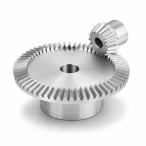
Straight Bevel Gear – M3 to M12, DIN6-9, Multi-Material
-
Differential Gears – Open, LSD, Torque Vectoring, Forged PM
-
Automotive Bevel Gear – M0.15 to M2.2, AGMA 13 / DIN 5
-
Spiral Bevel Gears – Helical Bevel Gear, Custom OEM Supply
-
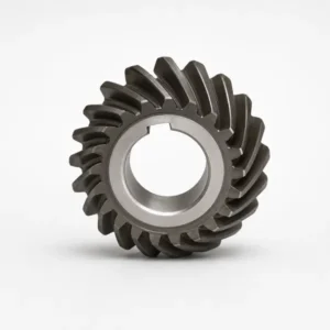
Industrial Bevel Gears – M3 to M20, Up to 1200mm Diameter
-
90 Degree Bevel Gears – Right-Angle Drive, All Materials
-
Sintered Metal Bevel Gears – Self-Lubricating, DIN 6–9
 English
  Italian
  Korean
  French
  Japanese