
Ground Helical Gears – DIN 4-6, M0.5-M10, Precision Ground
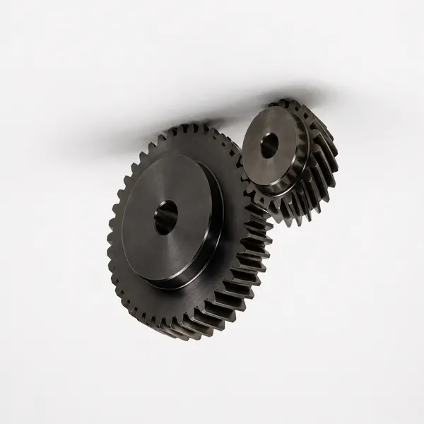
Korea Ever-Power ground helical gears are precision tooth-ground after heat treatment, delivering tighter dimensional accuracy, lower transmission error, and longer service life than hobbed or shaved helical gears. Available in 15° and 19°31′ helix angles, both left-hand and right-hand. Module 1 standard series and custom modules to drawing. Suitable for high-precision servo drives, CNC machine tools, rack-and-pinion systems, and any application requiring smooth, quiet, and accurate motion at the tooth mesh.
Product Overview
A ground helical gear is a helical gear whose tooth flanks are finish-ground after heat treatment. Where a hobbed or shaved helical gear carries the dimensional variation introduced by heat treatment distortion into service, a ground helical gear has that distortion corrected — the tooth profile, pitch spacing, and helix angle are remachined to final tolerance on the hardened blank. The result is tighter transmission error, lower noise at operating speed, and more predictable backlash behaviour over the gear's service life.
Korea Ever-Power produces ground helical gears in two standard helix angles — 15° and 19°31' — in both left-hand and right-hand configurations. The teeth of a ground helical gear are set at an angle to the axis of rotation, allowing teeth to mesh gradually rather than all at once, resulting in smoother and quieter operation than spur gears. The 19°31' ground helical gears are designed to run with racks with the same helix angle, making them the correct choice for helical rack-and-pinion systems requiring precise linear positioning.
A pair of reversed ground helical gears — one left-hand and one right-hand at the same helix angle — will rotate parallel shafts in opposite directions. A set of left-hand and right-hand 15° ground helical gears can also be used in place of spur gears where reduced noise and a small axial force on the shaft are acceptable. Korea Ever-Power's ground helical gears deliver smoother performance and greater longevity thanks to the precision tooth finish achievable only through grinding.
Technical Specifications
The example dimensions below are drawn from the standard production series. Custom modules, tooth counts, bore diameters, and hub dimensions are available to customer drawing.
| Ground Helical Gear — General Specifications | |
|---|---|
| Gear Type | Ground helical gear — parallel axis, external |
| Tooth Finishing | Tooth grinding after heat treatment (post-hardening grind) |
| Standard Helix Angles | 15° and 19°31' (19.5167°); custom angles per drawing |
| Helix Direction | Left-hand and right-hand — both available in each helix angle |
| Pressure Angle | 20° standard |
| Bore Type | Ground bore (precision); keyed bore or plain bore per drawing |
| Material | Alloy steel (standard); stainless steel, brass, aluminium per application |
| Heat Treatment | Carburising & quenching standard; through-hardening or nitriding per drawing |
| Rack Compatibility (19°31') | Designed to run with helical racks of the same 19°31' helix angle |
| OEM / ODM | Full service; customer drawings and samples accepted |
Example: Module 1, 100 Tooth, Left Hand, Ground Helical Gear
| Dimension | Value | Dimension | Value |
|---|---|---|---|
| Bore Type | Ground | Transverse Module | 1 |
| No. of Teeth | 100 | Direction of Helix | Left Hand |
| Shape | S1 | Helix Angle | 21°30' |
| Bore (A) | 15.0 mm | Pressure Angle | 20° |
| Hub Diameter (B) | 50.0 mm | Pitch Diameter (C) | 100.00 mm |
| Outer Diameter (D) | 102.00 mm | Face Width (E) | 8.0 mm |
| Hub Width (F) | 10.0 mm | Total Length (G) | 18.00 mm |
Advantages of Ground Helical Gears
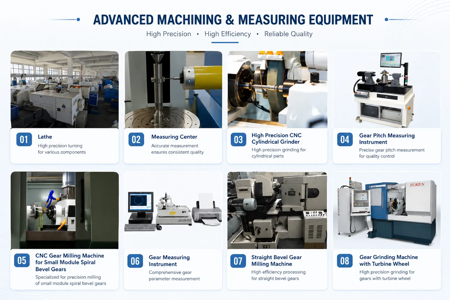
More Accurate Tooth Finish
Precision ground helical gears have a more precise tooth finish than machined or cut gears, providing smoother gear mesh for more controlled operation. Heat treatment distortion is corrected by the post-hardening grind, ensuring the delivered tooth profile matches the design drawing rather than the pre-hardening dimension plus unknown distortion.
More Material Options
While machining and other manufacturing processes may limit material choices, nearly any metal or alloy can be finish-ground to the required tooth profile. This allows the designer to select the best-suited material for the application — the optimum alloy for load, corrosion resistance, or weight — rather than the material that is easiest to machine.
Higher Loads & Better Performance
Ground helical gears can handle higher loads and higher stresses than gears produced by other means, because the post-hardening grind removes the soft skin or residual distortion that limits the load capacity of hobbed-and-hardened gears. Ground helical gears are particularly beneficial in large-torque applications where predictable long-term performance is required.
Smooth and Quiet Operation
Because helical teeth engage gradually rather than simultaneously across the full face width, load transfer is smooth and continuous. In ground helical gears, the tight tooth spacing tolerance means the periodic transmission error at the mesh frequency is minimised — the source of gear whine in high-speed drives. Ground helical gears running at servo speeds are typically inaudible above drivetrain background noise.
Compact Design Possible
Ground helical gears have excellent strength and wear resistance, allowing designs to be more compact. The higher tooth surface hardness and more accurate contact pattern of a ground gear distribute load more efficiently across the tooth face, enabling a smaller module or narrower face width to carry the same load as a larger hobbed gear — reducing gearbox size and weight.
Longer Service Life
The combination of high surface hardness, corrected tooth profile, and low surface roughness (Ra 0.4–0.8 μm after fine grinding) significantly reduces the pitting and wear rate at the tooth contact zone. Ground helical gears in well-lubricated gearboxes routinely operate for tens of thousands of hours without measurable tooth wear, far exceeding the service life of equivalent hobbed gears.
15° vs 19°31' — Choosing the Correct Helix Angle
15° Ground Helical Gear
The 15° helix angle produces a small axial force on shaft and bearings, making the gear mechanically similar to a spur gear in its bearing requirements while delivering the smoother, quieter engagement of a helical tooth. A left-hand and right-hand 15° ground helical gear pair can be used as a direct drop-in replacement for spur gears in applications where reduced noise is desired without a full redesign of the shaft and bearing arrangement. The 15° angle is the standard for ground helical gears used in general-purpose parallel-shaft speed reducers, servo gearheads, and precision instrument drives.
19°31' Ground Helical Gear
The 19°31' (19.5167°) helix angle is the standard for ground helical gears designed to mesh with helical racks of the same angle. In a helical rack-and-pinion system, the matching helix angle between pinion and rack eliminates the axial sliding component that appears when a spur pinion runs in a helical rack. This produces smoother linear motion, lower noise, and longer rack life. The 19°31' ground helical gear is the correct specification for high-precision CNC linear axes, coordinate measuring machine drives, and semiconductor wafer handling stages where smooth, accurate, and repeatable linear positioning is required.
Applications
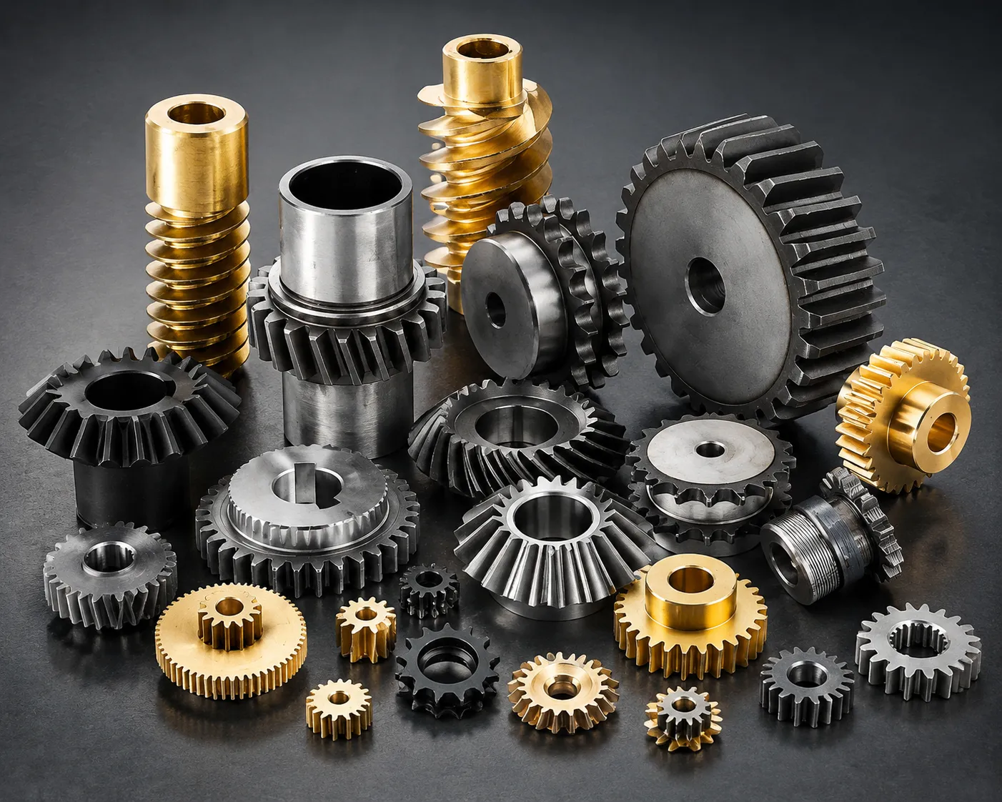
Servo Drives & Motion Control
Precision servo gearheads for robotics, CNC axes, and positioning stages. Ground tooth accuracy minimises transmission error and position ripple in closed-loop servo systems.
CNC Machine Tools
Spindle gearboxes and feed axis drives where tooth accuracy translates directly to workpiece positioning accuracy. 19°31' ground helical gears in helical rack-and-pinion linear axes for CNC machining centres.
Industrial Robotics
Joint drives in articulated industrial robots and collaborative robot arms. Ground helical gears provide the accuracy and low backlash required for repeatable path positioning in multi-axis robot trajectories.
Precision Instruments
Coordinate measuring machines, optical instrument drives, and semiconductor inspection stages where angular positioning accuracy is a primary specification. The tight transmission error of ground gears eliminates angular noise in scanning and indexing motions.
High-Speed Printing
Cylinder synchronisation drives in offset and flexographic printing presses. Transmission error in the gear stage appears as a repeating register error in the printed image — ground helical gears hold the error below the threshold of visual detection at commercial printing speeds.
Rack-and-Pinion Systems
19°31' ground helical pinions paired with helical racks of the same angle for gantry drives, machine tool linear axes, and automated guided vehicle guidance systems. The matching helix eliminates axial sliding noise and extends rack service life.
Quality Assurance
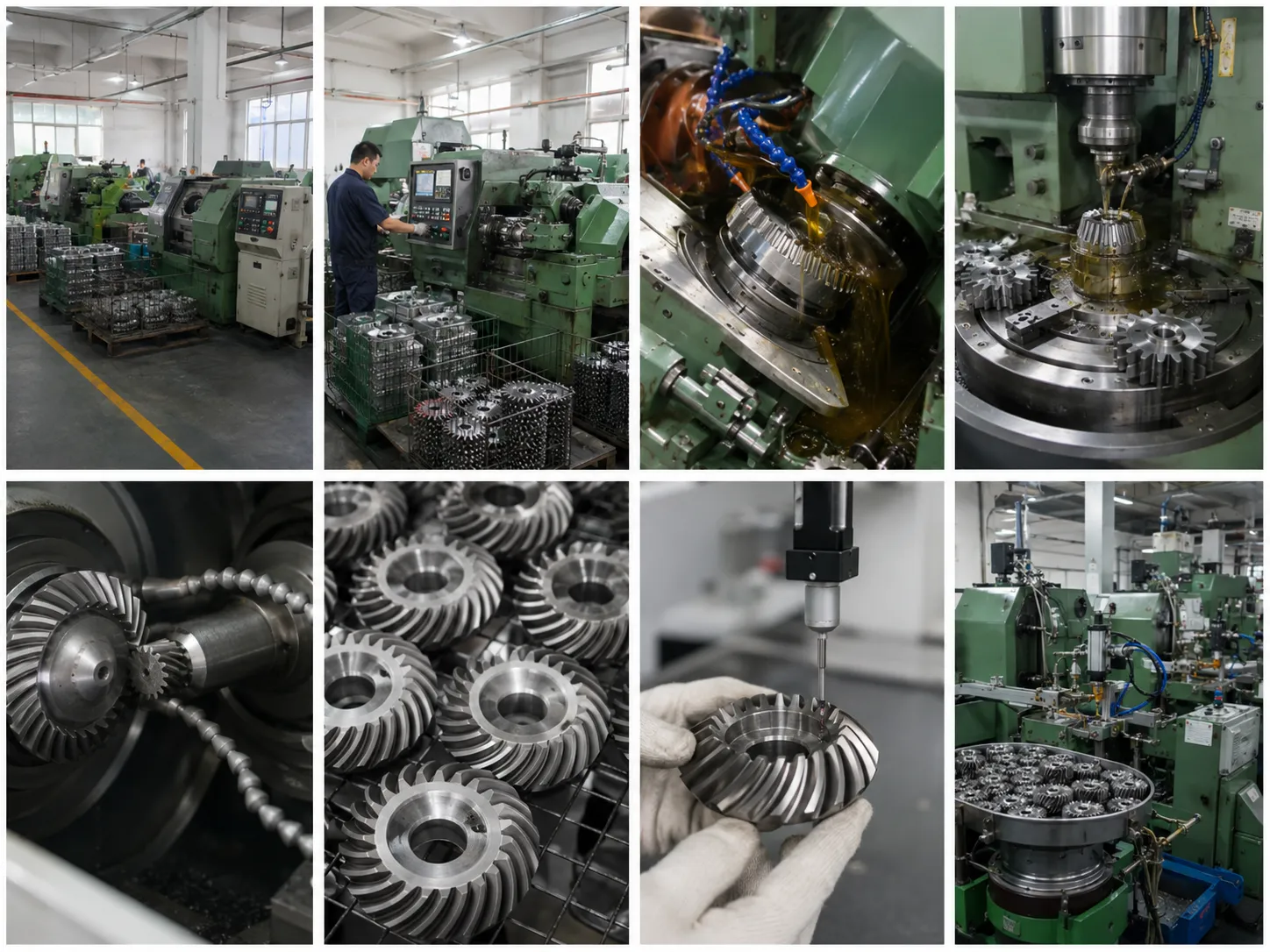
Korea Ever-Power verifies every ground helical gear against the following quality parameters before shipment:
- Tooth profile accuracy — CMM measurement of profile form deviation and single pitch deviation against the drawing tolerance. For high-accuracy grades, measurement is performed in a temperature-controlled environment.
- Helix angle verification — the ground helix angle is confirmed on a gear measurement machine. For 19°31' gears intended for helical rack systems, the helix angle is confirmed to the arc-minute to ensure correct meshing with the mating rack.
- Surface roughness — tooth flank roughness Ra measured after grinding. Standard ground finish: Ra 0.4–0.8 μm.
- Bore and OD concentricity — bore diameter, pitch diameter, and outer diameter verified against drawing dimensions with concentricity between bore axis and pitch cylinder confirmed.
- Material certificate — chemical composition certificate confirming the alloy grade; hardness test confirming surface and core hardness after heat treatment and grinding.
Frequently Asked Questions
What is the difference between a ground helical gear and a hobbed helical gear?
A hobbed helical gear is cut to profile and then heat-treated. Heat treatment introduces distortion — typically 0.05 to 0.3 mm of profile and pitch deviation depending on the gear size, material, and heat treatment method. This distortion remains in the finished gear and contributes to transmission error, noise, and uneven load distribution at the tooth contact. A ground helical gear is hobbed, heat-treated, and then finish-ground — the grinding removes the heat treatment distortion and restores the tooth profile to the design tolerance. The result is a gear with tighter transmission error, lower noise, and more accurate and predictable backlash than an equivalent hobbed gear.
Why are 19°31' ground helical gears specified for rack-and-pinion systems?
In a spur rack-and-pinion system, the contact between pinion tooth and rack tooth involves both rolling and sliding. The sliding component generates friction, noise, and wear at the tooth contact. In a helical rack-and-pinion system where the pinion helix angle matches the rack helix angle exactly, the sliding component is eliminated in the transverse plane — the tooth contact is purely rolling. The 19°31' angle is the industry standard for helical rack-and-pinion systems. Using a 19°31' ground helical pinion with a 19°31' helical rack produces quieter operation, lower wear, and longer system life than any spur rack-and-pinion combination at the same pitch.
Can left-hand and right-hand ground helical gears run on the same shaft?
Yes — this is a common configuration in gearboxes where two output shafts must rotate in opposite directions from one input. A left-hand ground helical gear and a right-hand ground helical gear of identical module and tooth count, mounted on the same input shaft and each meshing with a separate output gear, produce equal-speed opposite-direction output rotation. The axial thrust from the left-hand gear and the right-hand gear are equal and opposite, partially cancelling at the input shaft bearing and reducing the net axial bearing load compared with two single helical gears of the same hand.
What custom configurations are available beyond the standard module 1 series?
Korea Ever-Power produces ground helical gears to customer drawings in any module, tooth count, helix angle, bore diameter, and hub dimension. The standard 15° and 19°31' helix angles are the most common, but other angles — including custom angles for matching an existing mating rack or pinion — are available. Provide the drawing or a worn sample and our engineering team will confirm the specification and lead time.
How do I specify a ground helical gear for a servo drive application?
Provide the following: module, tooth count, helix angle and hand, pressure angle, bore diameter and type (ground, keyed, or splined), hub diameter, hub width, total length, and the required accuracy grade (DIN 5 or 6 for most servo applications). If the gear must mesh with a specific mating part — a pinion, a rack, or a second gear — provide the mating gear specification as well so the backlash can be controlled at the pair level rather than at the individual gear level. Contact our engineering team with these details and we will return a quotation within two working days.
Customer Reviews
"We build servo gearheads for collaborative robot joints and specified module 1 ground helical gear pairs at DIN 6 from Korea Ever-Power. The transmission error measured on our test rig is within 3 arc-seconds — better than the value from our previous supplier at the same accuracy grade. Backlash has remained stable through 500,000 duty cycles in our endurance test."
Jung Min-seok | Mechanical Design Lead, Suwon Robot Systems · Q1 2026
"We use 19°31' ground helical gears as pinions in the linear axis drive of our gantry machining centre. The gear noise dropped significantly when we switched from spur rack-and-pinion to the 19°31' helical system. Korea Ever-Power's helix angle measurement report confirmed the angle to within 0.5 arc-minutes — adequate for our rack mating requirements."
Oh Byeong-chan | Drive Systems Engineer, Daejeon Machine Tool Manufacturing · Q3 2025
"We replaced the hobbed helical gears in a high-speed printing press cylinder drive with ground helical gears from Ever-Power. Register accuracy improved from ±0.08 mm to ±0.03 mm at maximum press speed. The gear noise reduction was also immediately audible to the press operators. We have since specified ground helical gears as standard on all new press builds."
Lim Seong-ho | Press Drive Engineer, Gyeonggi Commercial Printing · Q4 2025
"We needed 15° left-hand and right-hand ground helical gear pairs as drop-in replacements for spur gears in a noise-sensitive instrument drive. Ever-Power produced to our drawing and provided helix angle measurement on both gears of each pair. Noise reduction at the mesh frequency was measured at 6 dB(A) — within our target of 5–8 dB."
Yoon Tae-jun | Acoustics Engineer, Seoul Precision Instruments · Q2 2025
"We source module 1 ground helical gears in stainless steel for semiconductor wafer handling robot joints — the gears must be cleanroom-compatible and non-magnetic. Ever-Power produced in 316L stainless with passivation and confirmed the helix angle, pitch accuracy, and surface roughness in the inspection report. Delivered within our programme timeline on both prototype and production batches."
Kwon Ji-young | Component Engineer, Suwon Semiconductor Handling Systems · Q1 2026
Related Products
Request a Quotation for Ground Helical Gears
Send us your module, tooth count, helix angle (15° or 19°31'), helix hand, bore diameter, and required accuracy grade. For rack-and-pinion applications, include the rack specification. Our engineering team returns a quotation within two working days.
Additional information
| Editor |
|---|
Related products
-
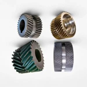
Double Helical Gear – Steel, OD up to 1370mm, Custom OEM
-
Metallurgy Machinery Soft Tooth Flank Helical Gear – ≤350HB
-
Double Helical Gears For Agricultural Machinery – 40Cr, HRC
-
Customized Double Helical Gear – OD 100-5000mm, OEM Design
-
High Speed Train Hard Tooth Flank Helical Gear – 56-62 HRC
-
Rolling Mill Double Helical Gear – 42CrMo, 50-55 HRC, OEM
-
Crossed Helical Gear (Screw Gear) – Right Angle, Custom OEM
-
Carbon Steel Double Helical Gear – 45#, Custom OD & Module
 English
  Italian
  Korean
  French
  Japanese