
Crossed Helical Gear (Screw Gear) – Right Angle, Custom OEM
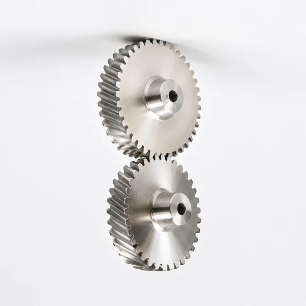
Korea Ever-Power crossed helical gears, also called screw gears, transmit motion between non-intersecting, non-parallel shafts at any shaft angle — including 90°. Unlike parallel helical gears where mating gears share equal but opposite helix angles, crossed helical gear pairs can have different helix angles on each gear, with their sum equalling the shaft crossing angle. Contact between meshing teeth is always point contact, making crossed helical gears suitable for light-load applications: machine tools, instrument drives, camshaft drives in small IC engines, elevator mechanisms, and indexing drives. Module M1–M12, materials including brass, steel, stainless, POM and aluminium. DIN 6–9. Sample $2–$100.
Product Overview
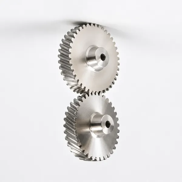
Crossed helical gears, sometimes called screw gears, are helical gears used in motion transmission between non-intersecting, non-parallel shafts. Where parallel axis helical gears require both shafts to run parallel, crossed helical gears allow the shaft axes to be oriented at any angle in space — the most common arrangement being 90°, but any other crossing angle is achievable. The shaft crossing angle equals the sum of the helix angles on the two mating gears when there is no profile shift.
A fundamental difference from parallel helical gears is that crossed helical gear pairs do not share the same helix angle. In parallel helical gears, mating gears must have identical helix angles in opposite hands. In crossed helical gears, the two gears may have different helix angles, and they may even share the same hand of helix — the geometry is defined by the shaft angle and the desired transmission ratio, not by the requirement for matching helix angles. This gives the designer significantly more freedom in specifying the gear geometry for a given shaft arrangement.
Crossed helical gears can also be shifted axially within relatively wide limits without negatively influencing power transmission — a useful property in applications where the axial position of one gear must be adjustable for assembly or backlash control without requiring complete disassembly of the gear pair. Korea Ever-Power produces crossed helical gears to customer drawings in module M1 to M12, in brass, C45 steel, stainless steel, copper, POM, aluminium, and alloy steel, to DIN 6 through DIN 9 precision grades.
Technical Specifications
| Crossed Helical Gear — Product Specifications | |
|---|---|
| Model / Module Number | M1, M1.5, M2, M2.5, M3, M4, M5, M8, M12, and others per drawing |
| Shaft Configuration | Non-intersecting, non-parallel shafts; shaft crossing angle = sum of helix angles (no profile shift) |
| Tooth Contact | Always point contact (not line contact); suitable for light-load applications |
| Helix Angle | Mating gears may have different helix angles; same or opposite hand — per shaft angle and ratio |
| Material | Brass, C45 steel, Stainless steel, Copper, POM, Aluminium, Alloy steel, and others per specification |
| Surface Treatment | Zinc-plated, Nickel plated, Passivation, Oxidation, Anodisation, Geomet, Dacromet, Black Oxide, Phosphatising, Powder Coating, Electrophoresis |
| Standard | ISO, DIN, ANSI, JIS, BS, and Non-standard |
| Precision Grade | DIN 6, DIN 7, DIN 8, DIN 9 |
| Teeth Treatment | Hardened, Milled, or Ground |
| Tolerance | 0.001 mm – 0.01 mm – 0.1 mm (per grade) |
| Finish | Shot/sandblast, heat treatment, annealing, tempering, polishing, anodising, zinc-plated |
| Lubrication | Hypoid gear oil or equivalent EP lubricant required — constant flank sliding demands adequate lubrication |
| Packing | Plastic bag + cartons, or wooden packing for larger gears |
| Payment Terms | T/T, L/C |
| Sample Lead Time | 20 business days; |
| Production Lead Time | 25 business days for bulk orders |
| OEM / Custom | Yes — drawings, samples, and reverse engineering accepted; metric and non-standard sizes available |
Application Sectors: Automatic controlling machines · Semiconductor industry · General industry machinery · Medical equipment · Solar energy equipment · Machine tools · Parking systems · High-speed rail and aviation transportation equipment
Geometry, Motion, and Key Features
The geometry of crossed helical gears produces a fundamentally different type of tooth motion from that of parallel helical gears. Understanding this distinction is essential to specifying and applying crossed helical gears correctly.
Screw Motion — No Pure Rolling
As the name "screw gear" suggests, crossed helical gears no longer exhibit pure rolling movement during engagement — instead, the tooth contact involves a screw motion. This means permanent sliding of the flanks occurs throughout the mesh cycle. In parallel helical gears, contact transitions from a point to a line as the teeth engage, and rolling dominates. In crossed helical gears, the contact remains point contact throughout, and the circumferential speeds of the two gears are not identical at any point on the contact. The reference bodies of crossed helical gears are not pitch cylinders but rotational hyperboloids — solids of revolution obtained by rotating a skew straight line around an axis.
Point Contact and Load Limitation
The permanent point contact between crossed helical gear teeth (in contrast to the progressive line contact of parallel helical gears) means the contact stress at the mesh point is very high for a given transmitted load. This limits crossed helical gears to light-load applications. Attempting to transmit heavy loads through crossed helical gears causes rapid surface fatigue pitting or scuffing at the contact point, far earlier than in equivalent parallel helical gears. The design torque for a crossed helical gear pair must be kept well below the value that would be acceptable for a parallel helical gear of the same module and face width.
Lubrication Requirement
The constant sliding of the flanks in crossed helical gear engagement requires special lubrication — hypoid gear oil or an equivalent extreme-pressure (EP) lubricant is the standard specification. Without adequate EP lubrication, the sliding contact generates heat and wear at a rate that is unacceptable for any sustained operation. The lubrication system must ensure the contact point is continuously supplied with fresh oil, as the sliding removes the boundary film rapidly. This requirement is one reason crossed helical gears are limited to applications where proper lubrication provision can be designed into the drive.
Low-Noise Operation
Despite the load limitations, crossed helical gears offer notably quiet operation — an advantage that makes them attractive in instrument drives and low-noise machine applications. The smooth, continuous screw-type tooth engagement, combined with the helical tooth form, eliminates the impact engagement characteristic of spur gears and produces a very smooth force transfer at the mesh point.
Axial Shiftability
Crossed helical gears can be shifted axially within relatively wide limits without negatively influencing power transmission. This is unlike parallel helical gears, where the face width limits the axial shift range, and unlike worm gears, where the worm and wheel must be precisely centred for correct tooth engagement. This axial freedom is useful in instrument and precision mechanism applications where the effective transmission ratio or backlash must be fine-tuned by small axial adjustments without full disassembly.
Parallel Helical Gear vs Crossed Helical Gear
| Parameter | Parallel Helical Gear | Crossed Helical Gear |
|---|---|---|
| Shaft arrangement | Parallel shafts only | Non-intersecting, non-parallel shafts — any crossing angle |
| Helix angle of mating gears | Same angle, opposite hand | May be different angles; same or opposite hand |
| Tooth contact type | Starts as point, becomes line contact | Always point contact |
| Tooth motion during mesh | Rolling dominant; sliding at tooth tips | Permanent sliding (screw motion) throughout mesh |
| Power transmission capacity | High — line contact distributes load | Low — limited by point contact stress |
| Efficiency | High (97–99%) | Lower — sliding losses reduce efficiency |
| Lubrication requirement | Standard gear oil | Hypoid / EP gear oil required |
| Noise level | Low | Very low |
| Axial shiftability | Limited to face width range | Wide axial shift range without affecting transmission |
| Typical applications | General industry; heavy and medium loads | Light loads; instruments; machine tools; camshaft drives; elevators |
Gear Transmission Maintenance
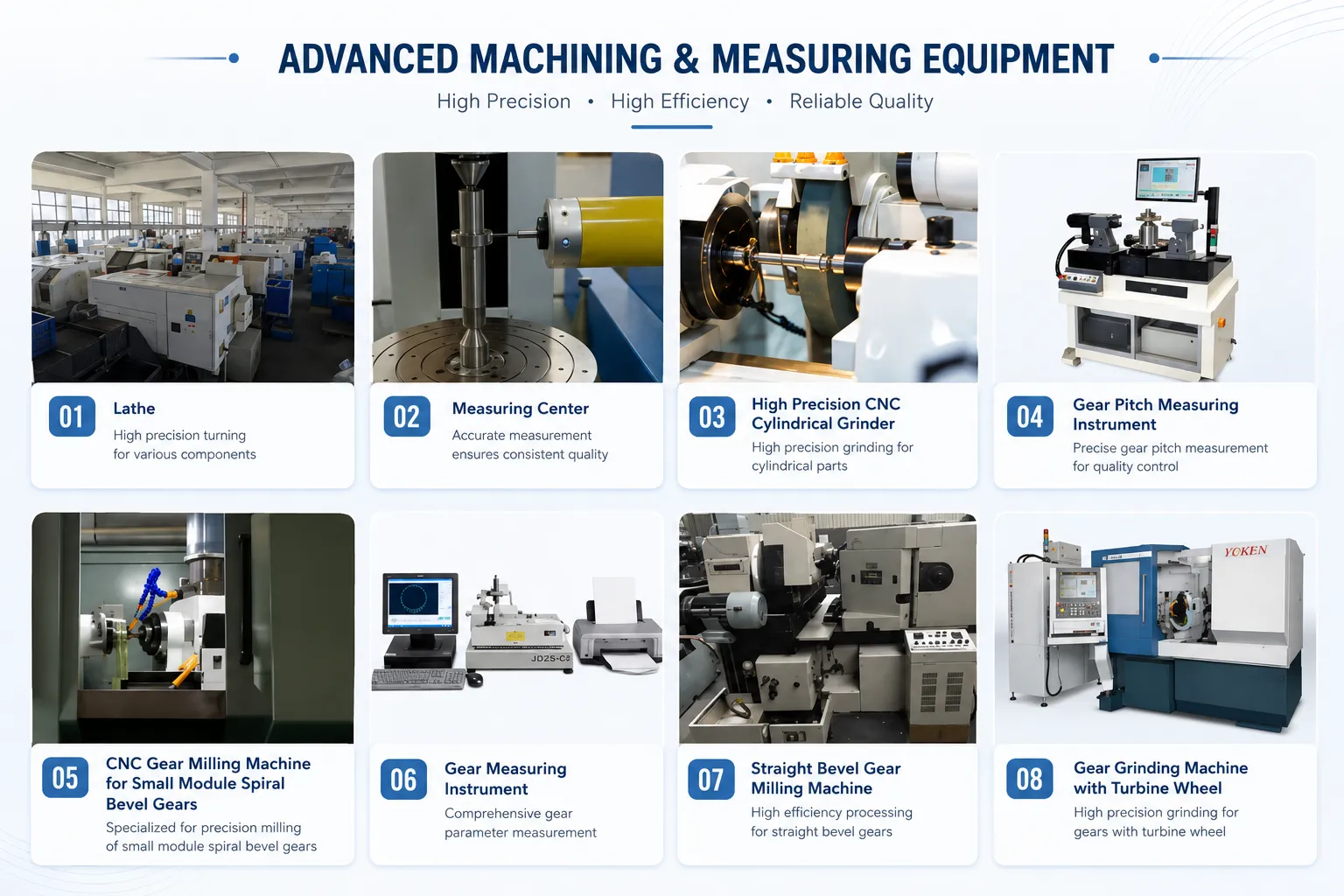
Proper maintenance is necessary for extending the service life of crossed helical gears. The daily maintenance programme should cover the following areas:
- Installation and running-in — fixing and positioning must meet the technical requirements for the shaft crossing angle and centre distance. Run a new pair of crossed helical gears for more than ten hours under no load and step-by-step loading before full service duty. After running-in, clean the housing and replace the oil before commencing loaded operation.
- Smooth operation practice — start-up, loading, unloading, and speed changes should be smooth to avoid impact loads. Impact loading on crossed helical gears causes accelerated wear at the contact point and can cause tooth surface scuffing even at loads below the continuous rating.
- Lubrication monitoring — check the lubrication system regularly: oil level, oil supply condition, and oil quality. The constant flank sliding in crossed helical gear engagement degrades the EP additive package in the gear oil faster than in parallel helical gear drives. Replace the oil at the intervals specified in the gearbox documentation, and supplement with the correct EP grade oil as needed. Never mix EP gear oils with different additive packages.
- Operating condition monitoring — watch, feel, and listen for abnormal sounds; check housing temperature. Abnormal noise or excessive temperature are early indicators of lubrication breakdown or contact point wear. Operating with detected faults ("working with fault") is prohibited — stop and inspect before continuing.
- Protective covers — for open crossed helical gear drives, install a protective cover to prevent dust, swarf, and other debris from reaching the tooth contact surface. Abrasive contamination at the contact point of a crossed helical gear pair causes rapid wear due to the continuous sliding contact. The cover also protects personnel from the rotating gear.
Applications
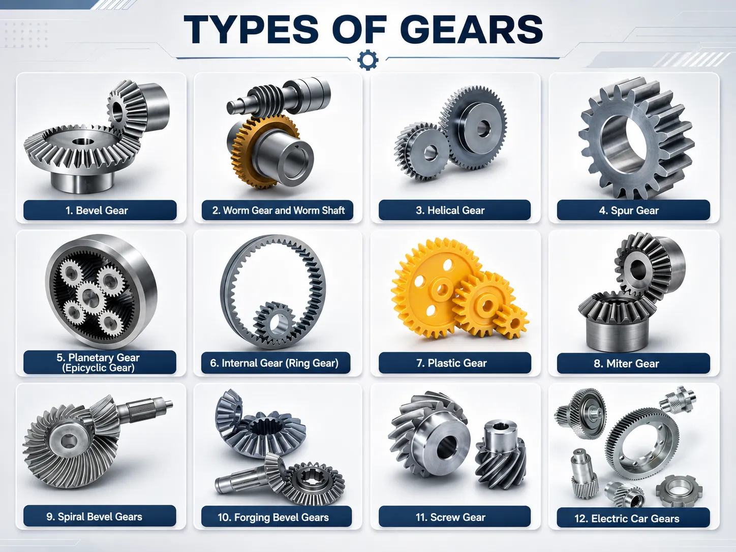
Lift / Elevator and Escalator Drives
Crossed helical gears are used in elevator and escalator drive mechanisms due to their compact size and the non-reversibility property: the gear pair cannot be backdriven easily from the output shaft, providing a natural load-holding capability in hoisting applications without additional braking devices.
Machine Tools
Indexing drives, cross-slide feeds, and auxiliary mechanism drives in machine tools where a non-parallel shaft angle is required and the transmitted load is light. The quiet operation and axial adjustability of crossed helical gears suit precision machine tool auxiliary drives.
Camshaft Drives in Small IC Engines
Small IC engine camshaft timing drives using crossed helical gears to transmit rotation from the crankshaft to the camshaft at a non-parallel shaft arrangement. The gear pair provides the 2:1 speed reduction with quiet, smooth operation and minimal backlash.
Precision Instruments
Small-size precision instrument drives — speedometers, angle encoders, and meter mechanisms — using crossed helical gears where very quiet operation, compact dimensions, and non-parallel shaft arrangement are simultaneously required.
Rudder and Marine Auxiliary
Light-duty rudder feedback drives and marine auxiliary mechanism drives where the non-intersecting shaft arrangement is fixed by the vessel's structural geometry. Stainless steel crossed helical gears with passivation for corrosion resistance in marine atmospheres.
Rolling Mills and Conveyors
Light auxiliary drives in rolling mills, presses, and conveying systems where a direction change between non-parallel shafts is required at low transmitted load. The main working drives use parallel helical or bevel gears; crossed helical gears serve the light auxiliary and positioning functions.
Frequently Asked Questions
What should I do if I cannot identify my existing crossed helical gear?
Send us the damaged or worn gear. Korea Ever-Power specialises in reverse engineering — our team will measure the outer diameter, tooth count, helix angle, hand of helix, bore, and hub dimensions, then prepare a production drawing for customer approval before cutting begins. For crossed helical gears, the helix angle measurement is critical because this determines the shaft crossing angle with the mating gear.
What inquiry information is needed to reply within 12 hours?
Korea Ever-Power normally quotes within 12 hours of receiving an inquiry (except national holidays). For a prompt quotation, provide: module, shaft crossing angle, helix angle and hand on each gear, tooth count on each gear, centre distance, bore type and diameter, material, precision grade, and required surface treatment. If you have a drawing, send it — this is the fastest path to an accurate quotation. For urgent enquiries, telephone contact is available during business hours.
Can crossed helical gears be manufactured in metric sizes or non-standard configurations?
Yes — Korea Ever-Power has the tools to manufacture crossed helical gears in any metric module size. Non-standard configurations — including non-standard helix angles, non-90° shaft crossing angles, and custom bore profiles — are fully supported. Everything is made to order against the customer's drawing or reverse-engineered from a sample. There are no standard stock catalogue items; every order is produced to the specific parameters provided.
How does the price of crossed helical gears vary with quantity?
Unit price decreases as quantity increases — the more parts ordered, the lower the per-unit price. The primary cost drivers are module size (which determines tooling and machine time), material grade, precision level, and required surface treatment. For a precise price at your required quantity, send us the drawing and quantity and we will provide a formal quotation with quantity-price tiers if applicable.
Can other materials besides steel be used for crossed helical gears?
Yes. Korea Ever-Power produces crossed helical gears in brass, C45 steel, stainless steel, copper, POM, aluminium, and alloy steel as standard material options. For brass crossed helical gears — often specified for instrument drives, marine applications, and non-magnetic environments — the material's self-lubricating properties under sliding contact are an advantage given the constant flank sliding inherent in crossed helical gear mesh. Contact our team with your application's material requirements and we will confirm suitability and price.
Customer Reviews
"We design indexing drives for automated assembly machines where the output shaft must run perpendicular to the drive motor. Korea Ever-Power produced M2 brass crossed helical gears to our drawing — the brass material gives us the self-lubrication and low noise we need in a sealed drive with limited maintenance access. Quotation came back within 12 hours of sending the drawing."
Kim Sang-wook | Mechanism Engineer, Incheon Assembly Automation · Q2 2026
"We manufacture precision speedometer mechanisms for specialised vehicles and use M1 stainless crossed helical gears at a 45°/45° shaft angle. The gears are essentially silent in operation — a critical requirement in an instrument cluster application. Ever-Power reverse-engineered the specification from our worn sample and supplied production drawing for approval before cutting."
Lee Chae-won | Instrument Design Engineer, Seoul Vehicle Instruments · Q4 2025
"We build elevator control mechanisms for low-rise residential buildings and use crossed helical gears in the position feedback drive — a non-parallel shaft arrangement that is dictated by the control panel geometry. The axial shiftability of crossed helical gears allowed us to fine-tune the backlash during installation without disassembling the drive. Ever-Power supplied M3 alloy steel to DIN 7 within the quoted lead time."
Park Bo-hyun | Control Systems Engineer, Gyeonggi Elevator Systems · Q1 2026
"We supply machine tool auxiliary drives with non-parallel shaft arrangements. Korea Ever-Power produced M1.5 POM crossed helical gears for a dry-running enclosed auxiliary drive where lubrication maintenance is impractical. The POM material handles the sliding contact well at our light transmitted load, and the gear noise is below the machine's background level."
Choi Yong-jin | Drive Components Buyer, Daegu Machine Tool Manufacturing · Q3 2025
"We could not identify our worn crossed helical gear pair from an old elevator feedback mechanism — no drawing available. Ever-Power measured the worn gear set and prepared a production drawing showing the helix angles on both gears and the shaft crossing angle. Drawing confirmed before production. Replacement set installed and operating correctly. Reverse engineering process took 5 working days from sample receipt to drawing submission."
Yoon Gi-tae | Maintenance Engineer, Busan Building Services · Q2 2025
Related Products
Request a Quotation for Crossed Helical Gears
Send drawing, shaft crossing angle, helix angles, module, material, and precision grade. For reverse engineering, send the worn gear. Quotation within 12 hours. Sample $2–$100; production 25 business days.
Additional information
| Editor |
|---|
Related products
-
Helical Angle 7° Internal Helical Ring Gear, DIN 4-8
-
Double Helical Gear – Steel, OD up to 1370mm, Custom OEM
-
Parallel Axis Helical Gears – Steel, Custom Module & Ratio
-
Carbon Steel Double Helical Gear – 45#, Custom OD & Module
-
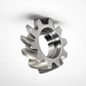
Beverage Packing Machinery Helical Gear – SS, Food Grade
-
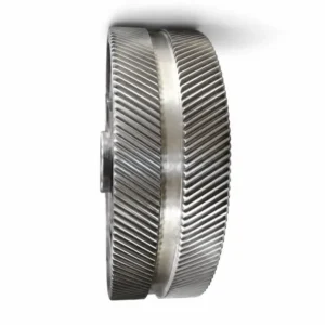
Double Helical Gears For Agricultural Machinery – 40Cr, HRC
-
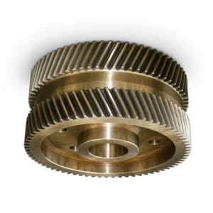
Heavy Machinery Double Helical Gear – 42CrMo, 50-55 HRC
-
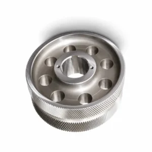
Industrial Double Helical Gears – Alloy Steel, OD to 1370mm
 English
  Italian
  Korean
  French
  Japanese