Double Helical Gears for Heavy Industry: Steel Mills, Cement Plants and Large Power Transmission
Double helical (herringbone) gears represent the pinnacle of large-scale power transmission engineering — combining the noise reduction and load capacity advantages of helical gear tooth contact with the unique ability to cancel axial thrust forces that would otherwise require massive, expensive thrust bearings on large shafts. From steel mill roughing stand gearboxes transmitting 20+ MW to cement mill ring-and-pinion open gears spanning 6 metres in diameter, double helical gears handle the most demanding power transmission requirements in heavy industry. This guide covers design principles, material specification, manufacturing challenges, and application engineering for double helical gears in steel, cement, mining, and large industrial gearbox applications.
Heavy industry double helical gear module range. Medium industrial gearbox (up to 5 MW): M10–M18. Steel mill roughing stand: M16–M28. Large cement mill pinion: M22–M36. Very large ship propulsion bull gear: M28–M40
POWER RANGE
1 – 30 MW
Double helical gears are the standard choice when single-helical gears would require excessively large thrust bearings or when bearing axial load rating is exceeded. Steel mill roughing stands: 5–25 MW. Cement ball mill drive: 2–8 MW. Large ship propulsion: 10–30 MW
HELIX ANGLE (PER SIDE)
20° – 35°
Helix angle per helix in a double helical gear pair. Higher helix angle increases contact ratio and reduces noise but increases the face width required for the central groove between helix halves. Standard heavy industrial double helical: 25°–30° per helix
FACE WIDTH
≥ 2× module × π / sin(ψ)
Minimum face width per helix for axial overlap ratio ≥ 1.0. At M20, helix 25°: minimum face per helix = 2 × 20 × π / sin(25°) = 298 mm per helix side, total ≥ 600 mm including central groove
The Engineering Case for Double Helical Gears in Heavy Industry
The decision to specify double helical gears instead of single helical gears in a heavy industrial drive is driven by a single dominant consideration: the axial thrust generated by a large single helical gear at high helix angle and high torque exceeds what is practical to absorb with rolling element or hydrodynamic thrust bearings on large, heavy shafts. At 25° helix angle and 5 MNm torque (typical for a steel mill roughing stand intermediate shaft), the axial thrust component on a single helical gear is Fa = Ft × tan(25°) = Ft × 0.466. For a 2,000 mm pitch diameter gear with 5 MNm torque, Ft = 5,000,000 ÷ 1.0 m = 5 MN, so Fa = 2.33 MN axial thrust — requiring a hydrodynamic thrust bearing capable of sustaining 2.33 MN continuously, a massive and expensive engineering challenge. The double helical gear, by combining left-hand and right-hand helices of equal hand and helix angle on the same gear body, generates equal and opposite axial thrust components that cancel within the gear mesh itself, reducing the net axial shaft force to the small residual from manufacturing helix angle error — typically less than 2% of the tangential force.
Korea Ever-Power’s double helical gears for heavy industry are manufactured in 18CrNiMo7-6 and 34CrNiMo6 case carburized (for gearbox gears requiring maximum fatigue life at high PLV), 42CrMo4 through-hardened (for medium-duty gearbox stages and slower-speed cement and mining drives), and 20MnCr5 (for replacement supply to existing heavy gearboxes where cost is the primary consideration). Large open gear pinions for cement mills and kilns are manufactured in 42CrMo4 QT (HB 270–320) with tooth surfaces induction hardened to HRC 52–56, allowing the pinion to be manufactured in sections for transport and assembled on-site if the pinion diameter exceeds road transport limits.
The manufacturing of double helical gears presents challenges not present in single helical gear production. The two helix halves must be hobbed or ground to exactly the same lead angle (same helix angle magnitude, opposite hand) and the phase relationship between the two halves — called the herringbone phase — must be maintained to within ±0.01 mm to avoid load concentration on one helix half. The central groove between the two helix halves must be wide enough to accommodate the hobbing cutter run-out and provide clearance for the mating gear’s axial float (a floating pinion is used in most herringbone gear applications to allow the pinion to self-centre under load). Korea Ever-Power machines double helical gears on dedicated CNC hobbing machines with automatic helix hand changeover, maintaining helix angle equality between left and right halves to ±0.01° and herringbone phase accuracy to ±0.015 mm on all production gears.
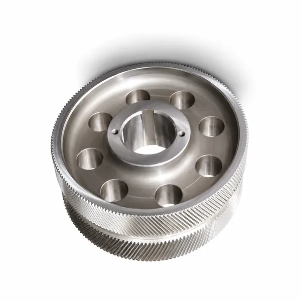
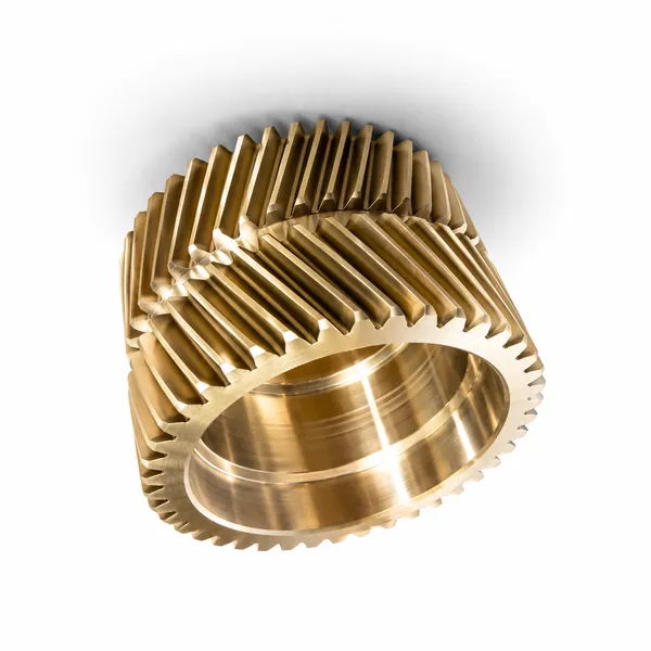
Korea Ever-Power industrial double helical (herringbone) gear for heavy-duty gearbox application — 42CrMo4 QT through-hardened HB 310–350, M18, left + right helix 28° per side, OD 920 mm, total face width 460 mm (2 × 210 mm helices + 40 mm central groove), DIN 6 quality class. Herringbone phase error ≤ 0.012 mm between left and right helix halves. Tooth surface Ra ≤ 0.8 μm after hobbing — ground finish available for DIN 5 on request. Used in steel mill gearbox intermediate stages and large industrial compressor bull gears where single-helical axial thrust would exceed thrust bearing capacity. Korea Ever-Power supplies matched double helical gear pairs for all major industrial gearbox brands including Renk, David Brown, and Elecon replacement programmes.
Heavy Industry Application Types
APP 01
STEEL MILL
ROLLING STAND
Double helical gear specification: M16–M28, 18CrNiMo7-6 or 34CrNiMo6 carburized, DIN 5–6 ground, 5–25 MW, helix 25°–30° per side, floating pinion arrangement to cancel residual axial force from helix angle manufacturing error. Steel rolling mills use double helical gearboxes (called pinion stands) at every rolling stage to convert the electric motor speed and torque to the rolling roll speed. The roughing mill pinion stands, which reduce large hot billets at high rolling force, transmit 5–25 MW per strand — at this power level and the moderate speed of roughing stands (100–400 RPM roll speed), the torque per gear is enormous. Double helical gears are mandatory because single-helical gears would generate axial forces exceeding 1 MN per gear on a roughing stand shaft, requiring hydrodynamic thrust bearings larger and more expensive than the gears themselves. The pinion stand also experiences severe cyclic torque variation as each roll pass begins and ends — the impact torque at rolling entry can exceed 3–4 times the steady rolling torque, requiring 18CrNiMo7-6 or 34CrNiMo6 for the core toughness needed to survive these shock cycles over the mill’s 20+ year design life. Korea Ever-Power supplies double helical replacement pinion gear sets for steel mill roughing, intermediate, and finishing stand gearboxes — contact with the mill OEM, pinion stand designation, and roll speed for specification and quotation.
APP 02
CEMENT MILL
GIRTH GEAR DRIVE
Double helical gear specification: M20–M36, pinion in 42CrMo4 QT HB 270–320 or 34CrNiMo6, girth gear (ring gear) in cast steel GS-42CrMo4, double helical tooth form on both pinion and girth gear, DIN 7–8, helix 15°–20° per side (lower helix angle than gearbox gears because girth gear diameter limits the practical helix without excessive groove width). Cement ball mills and vertical roller mills are driven through a girth gear (a large ring gear bolted to the mill shell) meshing with a pinion driven by the main gearbox. Ball mills above 3.5 MW use double helical girth gears and double helical pinions — at 5 MW and 3 RPM mill speed, the tangential force on a single-helical girth gear mesh would generate an axial force that the mill shell flange bolting cannot practically resist. The double helical arrangement balances this force within the mesh. Girth gears are large enough to require manufacture in segments (typically 4 or 8 segments per girth gear) for transport to site, with precision spigot-and-bolt joints maintaining concentricity after field assembly. Korea Ever-Power manufactures both cement mill pinions and segmented girth gears in the M20–M36 range, with field assembly measurement documentation and tooth contact pattern check procedures.
APP 03
LARGE SHIP
PROPULSION
Double helical gear specification: M22–M40, 18CrNiMo7-6 carburized or 42CrMo4 QT (for slower-speed cruise ship propulsion), DIN 5–6 ground, PLV 30–80 m/s at the high-speed stage pinion, helix 25°–35° per side, floating bull gear arrangement, classification society (DNV GL, BV, Lloyd’s) material and quality approval. Naval vessel and large merchant ship reduction gearboxes reduce the gas turbine or diesel prime mover speed (typically 3,000–10,000 RPM) to the propeller shaft speed (80–180 RPM) in two or three gear stages, transmitting 10–30 MW per shaft. The enormous bull gear of a naval or LNG carrier reduction gearbox — up to 5 m OD, 30+ tonnes, manufactured from a single forging — is virtually always double helical, because the alternative single-helical design at this scale would require a thrust bearing the size of a small house on the propeller shaft. These gears are manufactured to the most demanding specifications in the commercial gear industry — DIN 5 or better quality class, with individual tooth-by-tooth measurement reports, and class society surveyor witness inspection during manufacture, heat treatment, and final dimensional inspection before shipment.
APP 04
INDUSTRIAL
GEARBOX OEM
Double helical gear specification: M10–M22, 18CrNiMo7-6 carburized (high duty) or 42CrMo4 QT (standard duty), DIN 5–7, custom tooth geometry matched to gearbox housing bearing arrangement. Large enclosed industrial gearboxes for pump drives, fan drives, and generator drives above 2 MW commonly use double helical gear stages when the helix angle required for noise and load capacity targets would generate excessive bearing loads in single-helical form. The double helical enclosed gearbox has the advantage of simplified bearing arrangement — the pinion and wheel shaft bearings carry only radial load, because the axial thrust is self-contained within the double helical mesh. This allows smaller, lower-cost radial bearings on the gear shafts, with the cost and weight saving partly offsetting the higher cost of the double helical gears compared to single helical alternatives. Korea Ever-Power supplies double helical gear sets for industrial gearbox OEM production and for replacement supply to existing gearboxes from Renk (now RENK Group), David Brown (Timken Drives), Elecon Engineering, and Lufkin Industries (Baker Hughes).
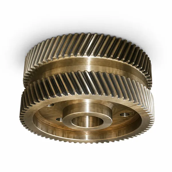
Korea Ever-Power large module double helical gear for heavy machinery application — 34CrNiMo6 carburized, M24, OD 1,850 mm, total face width 820 mm (2 × 380 mm + 60 mm groove), DIN 6 quality class. Manufactured from a single forged blank in one-piece construction for gearbox ratings below 12 MW per gear. Tooth root bending safety factor S_F ≥ 1.8 and contact fatigue safety factor S_H ≥ 1.25 per ISO 6336 at rated load. Individual gear measurement report per AGMA 915 covering all tooth geometry parameters, plus material certificate, heat treatment record, and MT/PT non-destructive examination report. Available for direct replacement of existing heavy industrial gearbox double helical gears with detailed reverse-engineering from existing gear dimensions.
Manufacturing Challenges Specific to Double Helical Gears
The manufacture of double helical gears involves several technical challenges that are absent in single helical or spur gear production, and which limit the number of manufacturers worldwide capable of producing large double helical gears to the required quality class. Understanding these challenges helps buyers make informed decisions about supplier capability assessment and quality verification.
Herringbone Phase Accuracy
The phase relationship between the left and right helix halves — measured as the angular offset of corresponding tooth spaces between the two sides — must be maintained within ±0.010–0.020 mm to ensure the two helix halves make contact at precisely the same position in the tooth mesh cycle. Phase error causes one helix half to carry more load than the other (the half with smaller phase error contacts first and must share the load with the other half before the second half makes contact). At large modules, a phase error of 0.030 mm between helix halves can shift the load ratio to 60:40 instead of the assumed 50:50, increasing the maximum stress on the leading helix half by 20% and potentially causing premature fatigue failure. Korea Ever-Power measures herringbone phase error using a dedicated CMM fixture that simultaneously contacts both helix half tooth surfaces at the same axial position.
Target: ≤ 0.015 mm phase error
Central Groove Design and Cutter Run-Out
The central groove between the two helix halves must be wider than the hobbing cutter’s run-out path at the end of each helix (the cutter must exit the tooth form at the groove before the helix direction reverses). Minimum central groove width = hobbing cutter OD × sin(helix angle) + clearance. At M20 and helix 28°, hobbing cutter OD ≈ 180 mm: minimum groove = 180 × sin(28°) + 5 = 84 + 5 = 89 mm. Central groove width must also accommodate the axial float of the floating pinion (typically ±5 mm for large herringbone gearboxes). A groove that is too narrow prevents clean hob exit and leaves undercut in the tooth form adjacent to the groove; a groove that is too wide wastes face width and reduces the tooth’s load-sharing between the two helices. Korea Ever-Power calculates the minimum groove width for each double helical gear from the module, helix angle, and cutter geometry before hobbing tool selection.
Typical groove: 1.5–3× module per helix angle
Heat Treatment Distortion Control
Large double helical gears in 18CrNiMo7-6 or 34CrNiMo6 are case carburized at 900–950°C and then oil-quenched — a process that causes dimensional distortion from the thermal gradient between the case and core during rapid cooling. The distortion of a large double helical gear typically manifests as differential growth of the two helix halves — because the mass distribution of the central groove region creates a local temperature gradient at quench that affects the two sides unequally. This distortion must be corrected by post-quench grinding of both tooth flank surfaces and the bore. For large gears (OD above 800 mm) where grinding is not practical across the full face width, through-hardening with 42CrMo4 (which requires no quench from high temperature) is used instead of carburizing, accepting the lower tooth hardness in exchange for better dimensional control. Korea Ever-Power pre-distorts the hobbing path for large carburized double helical gears based on measured distortion data from previous similar gear heat treatments, reducing the post-quench material removal required in grinding.
Key: carburize vs. through-harden selection
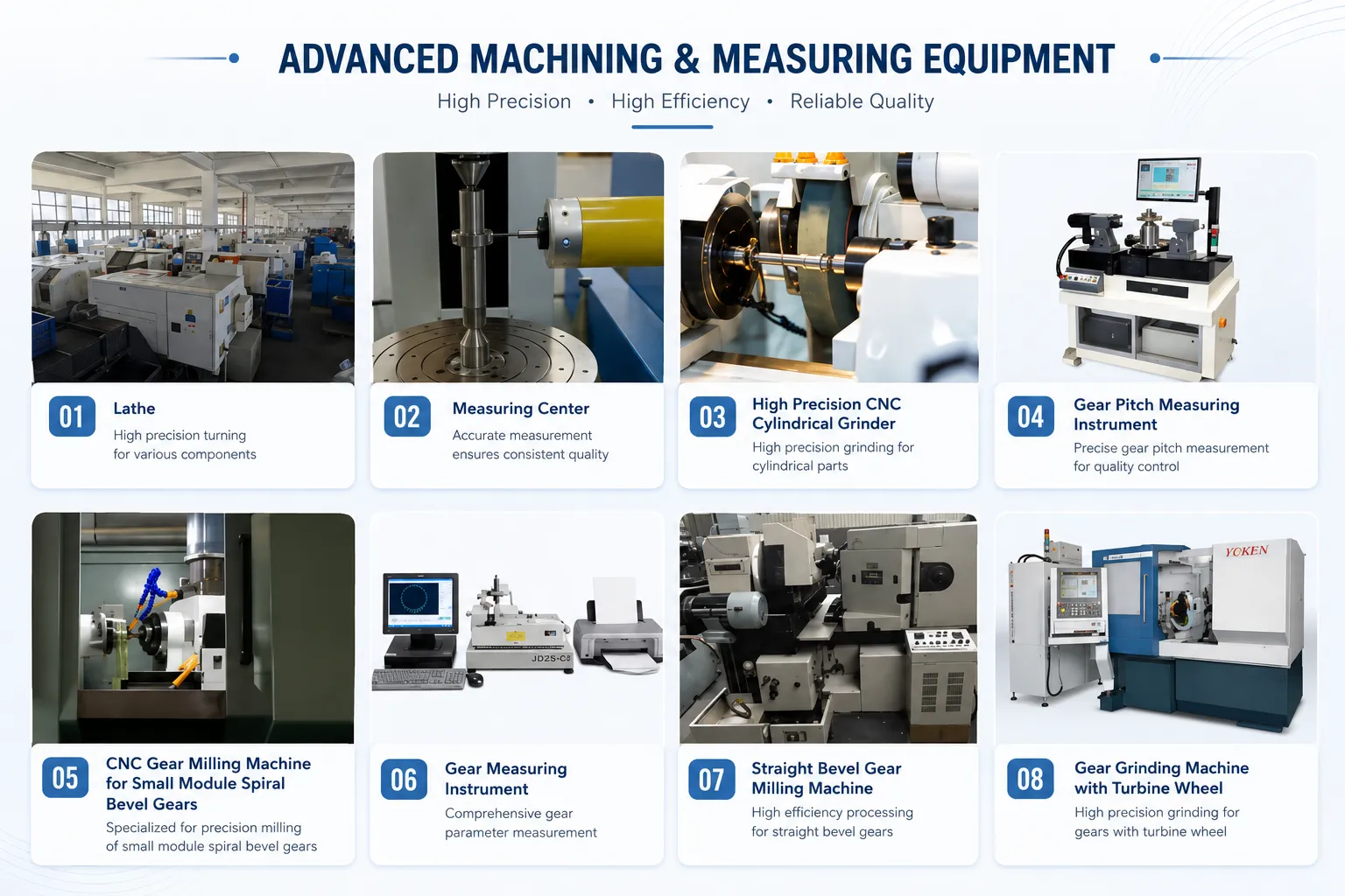
Korea Ever-Power gear measurement and quality control facility — CNC coordinate measuring machine (CMM) for large gear profile, lead, and spacing measurement on double helical gears up to 2,500 mm OD. All large module double helical gears receive 100% tooth measurement on dedicated CMM equipment, with individual tooth reports submitted to the customer before shipment as part of the quality documentation package. Korea Ever-Power’s measurement programme covers: profile form error ff-α, profile slope deviation fH-α, lead form error ff-β, lead slope deviation fH-β, pitch deviation fp and Fu, cumulative pitch error Fp, runout Fr, herringbone phase error — all per DIN 3960/3962 or AGMA 915-1-A02 as specified by the customer.
Frequently Asked Questions — Double Helical Gears for Heavy Industry
Q 01
When should I choose double helical gears over single helical gears for a new heavy industrial gearbox design, and what design changes are needed to accommodate them?
The choice between single helical and double helical gears for a heavy industrial gearbox comes down to three assessment criteria: (1) Axial thrust vs bearing capacity: calculate the axial thrust of the proposed single helical gear at the maximum helix angle and rated torque. If this thrust exceeds 30–40% of the available thrust bearing axial dynamic load rating Ca in the current bearing arrangement, double helical is recommended to eliminate the thrust. (2) Shaft deflection from axial load: on long shafts (shaft L/D above 8:1), the axial force from a single helical gear bends the shaft and shifts the tooth contact to the tooth ends — this aggravates the lead contact pattern and concentrates stress at the tooth edges. Double helical eliminates this effect by self-cancelling thrust. (3) Noise specification: at the same helix angle, double helical gears have a higher total contact ratio than single helical (because both helix halves contribute independently), reducing transmission error and noise by 2–4 dB(A) vs single helical. Design changes needed for double helical accommodation: the gearbox housing must accommodate the wider total face width (both helices plus central groove) — typically 2.5–3× the single helical face width for the same load capacity at the same helix angle. One shaft (usually the pinion shaft) must be allowed axial float of ±5–10 mm to permit the double helical mesh to self-centre under load — this precludes a fixed thrust bearing on the pinion shaft and requires an axially floating bearing arrangement. Korea Ever-Power can assist with the axial thrust calculation and gear sizing for new double helical gearbox designs — contact with the required transmitted power, input and output speeds, and available housing envelope dimensions.
Q 02
What causes one helix half to wear faster than the other in a double helical gear set, and how is this diagnosed and corrected?
Unequal wear between the left and right helix halves of a double helical gear is the most common failure mode in herringbone gear sets and has four root causes: (1) Herringbone phase error exceeding 0.015 mm: the leading half contacts first and carries disproportionate load. Diagnose by blue-marking contact pattern — the leading half shows wider tooth contact width than the lagging half. Correct by remanufacturing with tighter phase control, or by selective shimming of the housing to shift the floating pinion toward the lagging half. (2) Helix angle inequality between halves: if left helix angle ≠ right helix angle (even by 0.01°), the self-centering force of the floating pinion will push it toward the side with the smaller helix angle (which generates less axial separating force), overloading that side. Diagnose by lead measurement on both halves — the helix angles should be identical to within ±0.01°. Correct by remanufacturing the affected half to the correct helix angle. (3) Housing bore parallelism error: if the pinion and wheel shaft bearing housings are not parallel within 0.01 mm per 1,000 mm shaft length, the tooth contact on both halves shifts toward the high-side edge, concentrating stress in one area of both helices simultaneously. Diagnose by contact pattern under blue marking — both halves show edge contact on the same side. Correct by re-scraping or re-boring the bearing housing to correct parallelism. (4) Insufficient pinion float: if the floating pinion’s axial movement is restricted by a misaligned floating bearing arrangement, the pinion cannot self-centre and one helix half carries the majority of the load. Check pinion axial float by measuring the float range with feeler gauges — minimum float should be ±3 mm for industrial gearboxes, ±5 mm for mill gearboxes. Korea Ever-Power can analyse failure mode from tooth contact pattern photographs and gear measurement data — contact with high-resolution contact pattern photographs and the gear measurement reports for a specific failure analysis.
Q 03
What is the lead time and documentation package for large double helical gear replacement sets for a steel mill pinion stand or cement mill girth gear drive?
Lead time and documentation for large double helical replacement gear sets from Korea Ever-Power: Steel mill pinion stand (M16–M24, 18CrNiMo7-6 carburized, DIN 6 ground): 50–70 days from confirmed drawing or reverse-engineering measurement to shipment. This allows 7–10 days for forging procurement, 15–20 days for rough machining and heat treatment, 15–20 days for finish machining and grinding, and 5–7 days for final inspection and documentation. Cement mill pinion (M22–M30, 42CrMo4 QT, induction-hardened tooth surface): 55–75 days. Documentation package for each order: material mill certificate (chemical composition and mechanical properties with forging identity traceability); heat treatment record (carburizing atmosphere curve and quench temperature–time record, or through-hardening and tempering records); dimensional inspection report (all drawing dimensions confirmed, including herringbone phase error measurement); tooth profile and lead measurement report per DIN 3960 or AGMA 915 for all measured tooth positions; surface hardness report (minimum 5 tooth positions, HRC value and case depth from surface hardness traverse); non-destructive examination report (magnetic particle or dye penetrant on all tooth flanks and roots, confirming no indications); photographic record (gear blank after forging, after machining, and after heat treatment); and ISO 9001:2015 quality management system certificate. For steel mill and cement plant orders requiring third-party inspection agency witness (Bureau Veritas, TÜV, SGS, or similar), Korea Ever-Power can arrange inspection at Korea Ever-Power’s facility at an additional 7–10 days to the lead time for scheduling the inspector’s visit.
Explore Korea Ever-Power Gear Categories
Seven precision gear product lines for heavy industry, energy, marine and specialist applications worldwide.
Korea Ever-Power manufactures 18CrNiMo7-6, 34CrNiMo6, and 42CrMo4 double helical gears for all heavy industrial applications — steel mill pinion stands, cement mill girth gear drives, large ship propulsion gearboxes, and industrial gearbox OEM supply. Module M10–M40, face width up to 1,200 mm, DIN 5–7 quality class. Full material, heat treatment, dimensional, and NDE documentation package standard. Replacement for Renk, David Brown, Elecon, and all major industrial gearbox brands. ISO 9001:2015 certified.

 Korean
  English
  Italian
  French
  Japanese