
Double Helical Gears for Heavy Industry:
Steel Mills, Cement Plants and Large Power Transmission
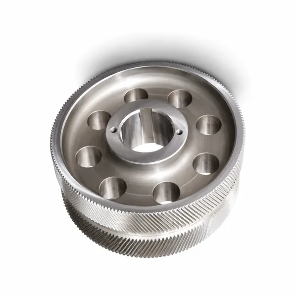
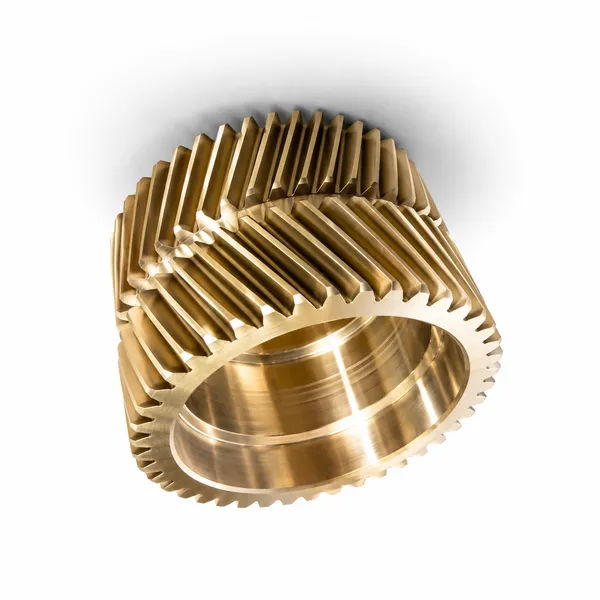
Double helical (herringbone) gears represent the pinnacle of large-scale power transmission engineering — combining the noise reduction and load capacity advantages of helical gear tooth contact with the unique ability to cancel axial thrust forces that would otherwise require massive, expensive thrust bearings on large shafts. From steel mill roughing stand gearboxes transmitting 20+ MW to cement mill ring-and-pinion open gears spanning 6 metres in diameter, double helical gears handle the most demanding power transmission requirements in heavy industry. This guide covers design principles, material specification, manufacturing challenges, and application engineering for double helical gears in steel, cement, mining, and large industrial gearbox applications.
M10–M40 · Zero Axial Thrust · DIN 5–7
Steel Mill · Cement · Mining · Ship Propulsion
The Engineering Case for Double Helical Gears in Heavy Industry
The decision to specify double helical gears instead of single helical gears in a heavy industrial drive is driven by a single dominant consideration: the axial thrust generated by a large single helical gear at high helix angle and high torque exceeds what is practical to absorb with rolling element or hydrodynamic thrust bearings on large, heavy shafts. At 25° helix angle and 5 MNm torque (typical for a steel mill roughing stand intermediate shaft), the axial thrust component on a single helical gear is Fa = Ft × tan(25°) = Ft × 0.466. For a 2,000 mm pitch diameter gear with 5 MNm torque, Ft = 5,000,000 ÷ 1.0 m = 5 MN, so Fa = 2.33 MN axial thrust — requiring a hydrodynamic thrust bearing capable of sustaining 2.33 MN continuously, a massive and expensive engineering challenge. The double helical gear, by combining left-hand and right-hand helices of equal hand and helix angle on the same gear body, generates equal and opposite axial thrust components that cancel within the gear mesh itself, reducing the net axial shaft force to the small residual from manufacturing helix angle error — typically less than 2% of the tangential force.
Korea Ever-Power’s double helical gears for heavy industry are manufactured in 18CrNiMo7-6 and 34CrNiMo6 case carburized (for gearbox gears requiring maximum fatigue life at high PLV), 42CrMo4 through-hardened (for medium-duty gearbox stages and slower-speed cement and mining drives), and 20MnCr5 (for replacement supply to existing heavy gearboxes where cost is the primary consideration). Large open gear pinions for cement mills and kilns are manufactured in 42CrMo4 QT (HB 270–320) with tooth surfaces induction hardened to HRC 52–56, allowing the pinion to be manufactured in sections for transport and assembled on-site if the pinion diameter exceeds road transport limits.
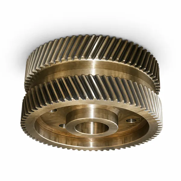
The manufacturing of double helical gears presents challenges not present in single helical gear production. The two helix halves must be hobbed or ground to exactly the same lead angle (same helix angle magnitude, opposite hand) and the phase relationship between the two halves — called the herringbone phase — must be maintained to within ±0.01 mm to avoid load concentration on one helix half. The central groove between the two helix halves must be wide enough to accommodate the hobbing cutter run-out and provide clearance for the mating gear’s axial float (a floating pinion is used in most herringbone gear applications to allow the pinion to self-centre under load). Korea Ever-Power machines double helical gears on dedicated CNC hobbing machines with automatic helix hand changeover, maintaining helix angle equality between left and right halves to ±0.01° and herringbone phase accuracy to ±0.015 mm on all production gears.
Heavy Industry Application Types
Manufacturing Challenges Specific to Double Helical Gears
The manufacture of double helical gears involves several technical challenges that are absent in single helical or spur gear production, and which limit the number of manufacturers worldwide capable of producing large double helical gears to the required quality class. Understanding these challenges helps buyers make informed decisions about supplier capability assessment and quality verification.
Herringbone Phase Accuracy
The phase relationship between the left and right helix halves — measured as the angular offset of corresponding tooth spaces between the two sides — must be maintained within ±0.010–0.020 mm to ensure the two helix halves make contact at precisely the same position in the tooth mesh cycle. Phase error causes one helix half to carry more load than the other (the half with smaller phase error contacts first and must share the load with the other half before the second half makes contact). At large modules, a phase error of 0.030 mm between helix halves can shift the load ratio to 60:40 instead of the assumed 50:50, increasing the maximum stress on the leading helix half by 20% and potentially causing premature fatigue failure. Korea Ever-Power measures herringbone phase error using a dedicated CMM fixture that simultaneously contacts both helix half tooth surfaces at the same axial position.
Target: ≤ 0.015 mm phase error
Central Groove Design and Cutter Run-Out
The central groove between the two helix halves must be wider than the hobbing cutter’s run-out path at the end of each helix (the cutter must exit the tooth form at the groove before the helix direction reverses). Minimum central groove width = hobbing cutter OD × sin(helix angle) + clearance. At M20 and helix 28°, hobbing cutter OD ≈ 180 mm: minimum groove = 180 × sin(28°) + 5 = 84 + 5 = 89 mm. Central groove width must also accommodate the axial float of the floating pinion (typically ±5 mm for large herringbone gearboxes). A groove that is too narrow prevents clean hob exit and leaves undercut in the tooth form adjacent to the groove; a groove that is too wide wastes face width and reduces the tooth’s load-sharing between the two helices. Korea Ever-Power calculates the minimum groove width for each double helical gear from the module, helix angle, and cutter geometry before hobbing tool selection.
Typical groove: 1.5–3× module per helix angle
Heat Treatment Distortion Control
Large double helical gears in 18CrNiMo7-6 or 34CrNiMo6 are case carburized at 900–950°C and then oil-quenched — a process that causes dimensional distortion from the thermal gradient between the case and core during rapid cooling. The distortion of a large double helical gear typically manifests as differential growth of the two helix halves — because the mass distribution of the central groove region creates a local temperature gradient at quench that affects the two sides unequally. This distortion must be corrected by post-quench grinding of both tooth flank surfaces and the bore. For large gears (OD above 800 mm) where grinding is not practical across the full face width, through-hardening with 42CrMo4 (which requires no quench from high temperature) is used instead of carburizing, accepting the lower tooth hardness in exchange for better dimensional control. Korea Ever-Power pre-distorts the hobbing path for large carburized double helical gears based on measured distortion data from previous similar gear heat treatments, reducing the post-quench material removal required in grinding.
Key: carburize vs. through-harden selection
Frequently Asked Questions — Double Helical Gears for Heavy Industry
Explore Korea Ever-Power Gear Categories
Seven precision gear product lines for heavy industry, energy, marine and specialist applications worldwide.
Editor: Cxm
 English
  Italian
  Korean
  French
  Japanese