
GEAR APPLICATION GUIDE · WORM GEAR · W01
Worm Gears for Valve Actuators:
Self-Locking Design and Torque Output
Worm gear actuators are the dominant drive type for industrial valve control — their self-locking property holds the valve position without power, and their single-stage reduction ratios of 10:1 to 100:1 convert low-torque motor output to the high torque required to seat gate valves, butterfly valves, and ball valves against full line pressure.
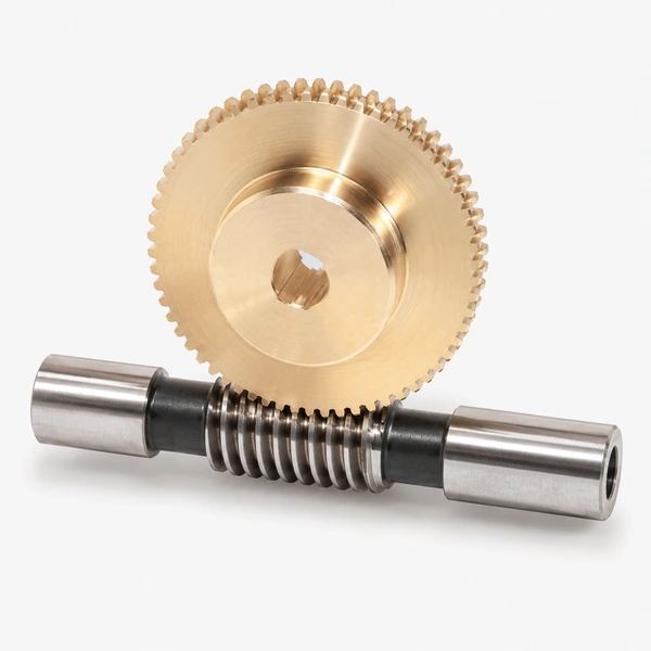
Bronze Wheel · Stainless Worm · ISO 9001
Gate · Butterfly · Ball · Globe Valve
Why Worm Gears Are the Standard for Valve Actuators
The worm gear is the dominant drive mechanism for industrial valve actuation for three engineering reasons that no other gear type simultaneously provides: high single-stage reduction ratio (eliminating the multi-stage gear trains that spur or helical gear actuators require), self-locking property (the valve remains in its last position when the actuator motor is de-energised, without any brake mechanism), and compact 90° right-angle drive geometry (allowing the actuator to be mounted directly to the valve stem with a minimal footprint regardless of valve size or orientation).
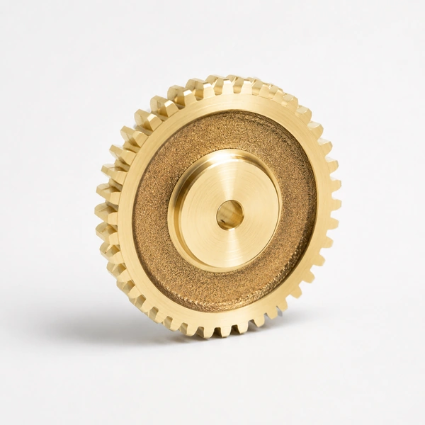
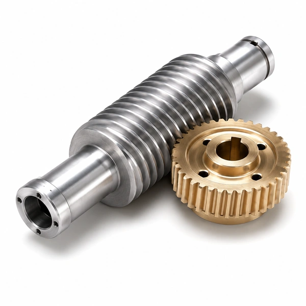
Korea Ever-Power’s worm gears for valve actuators cover single-start to four-start worm gear sets in phosphor bronze wheel and 20CrMnTi or 42CrMo4 hardened steel worm — reduction ratios from 10:1 to 100:1 in a single stage, output torques from 50 Nm to over 50,000 Nm for the full range of industrial valve actuation requirements from DN50 gate valves to DN1000 butterfly valves on large diameter pipelines.
The self-locking characteristic of worm gears at lead angles below approximately 6° (corresponding to worm gear ratios above 20:1 for single-start worms) is the key safety property for valve actuation: a motor failure or power interruption does not cause the valve to open or close under pipeline pressure. This fail-safe position-holding behaviour is a regulatory requirement for many critical valve applications in oil and gas, water treatment, chemical plant, and power generation — applications where the cost of an uncontrolled valve movement far exceeds the cost of the worm gear actuator itself.
Self-Locking — The Safety Property
A worm gear is self-locking when the lead angle of the worm thread is less than the friction angle at the worm-wheel contact (approximately arctan(μ), where μ is the friction coefficient ≈ 0.08–0.15 for lubricated bronze-on-steel). Self-locking occurs when lead angle < arctan(0.10) ≈ 5.7° — corresponding to gear ratios above approximately 20:1 for single-start worms. At these ratios, a reverse torque applied to the wheel output shaft cannot back-drive the worm, because the reaction force at the worm thread helix produces a contact normal force that generates more friction than the thread can overcome. The valve stays closed under line pressure without motor holding torque or mechanical brake.
High Ratio, Compact Package
A worm gear set achieves 10:1 to 100:1 reduction in a single stage — a ratio that would require three or four stages of spur or helical gearing. This compactness is critical for valve actuators that must fit within the restricted space of a process plant valve manifold. The 90° right-angle geometry of the worm gear — worm input shaft perpendicular to worm wheel output shaft — directly matches the typical valve actuator mounting arrangement where the electric motor shaft is horizontal and the valve stem is vertical.
Bronze Wheel — Essential for Life
The worm gear contact involves significant sliding velocity between the worm thread and the wheel tooth — much higher sliding than in spur or helical gear contacts. Phosphor bronze (PB2 or AB2 centrifugal cast) for the worm wheel is the standard material choice because its excellent anti-galling property prevents seizure at the high sliding contact, its sacrificial wear behaviour protects the hardened steel worm, and its self-lubricating property (through the absorbed lubricant in the porous bronze microstructure) reduces the sensitivity to lubricant film breakdown during infrequent valve cycling that can damage lubrication-dependent steel-on-steel contacts.
Worm Gear Actuator Design: Ratio, Torque and Self-Locking
ACTUATOR OUTPUT TORQUE CALCULATION
Motor Torque → Valve Torque
Tout = Tmotor × i × η where Tmotor is motor output torque (Nm), i is worm gear ratio, η is worm gear efficiency. Example: 5 Nm motor, 40:1 ratio, η = 60%: Tout = 5 × 40 × 0.60 = 120 Nm. This output torque must exceed the valve maximum seating torque including a service factor of 1.3–1.5 for valve wear and line pressure variation.
Valve Seating Torque
Gate valve seating torque (Nm) ≈ 0.05 × DN × P, where DN is valve nominal diameter (mm) and P is line pressure (bar). Example: DN300 gate valve at 16 bar: Tseat ≈ 0.05 × 300 × 16 = 240 Nm. With service factor 1.4: design torque = 336 Nm. At worm gear ratio 40:1, η = 60%: motor required = 336 / (40 × 0.60) = 14 Nm motor torque.
Back-Driving Torque Check
For self-locking verification: back-driving torque required Tbd = Tout × (tan(λ − ρ) / tan(λ + ρ)) where λ = lead angle, ρ = friction angle. If this value is negative, the gear is self-locking. At ratio 40:1 (λ = 1.4°) with μ = 0.10 (ρ = 5.7°): tan(1.4° − 5.7°) is negative → self-locking confirmed. Korea Ever-Power confirms self-locking status for every worm gear valve actuator order.
Valve Actuator Applications by Valve and Process Type
Frequently Asked Questions
Explore Korea Ever-Power Gear Categories
Seven precision gear product lines for industrial, process, automotive and specialist applications worldwide.
編集者: Cxm
 Japanese
  English
  Italian
  Korean
  French