
Helical Gears for Industrial Gearboxes:
Noise Reduction and Load Capacity Guide
Helical gears are the dominant gear type in industrial gearbox design — offering higher contact ratios, smoother torque transmission and 6–10 dB(A) lower noise than equivalent spur gears. This guide covers helix angle selection, axial thrust management, material specification, DIN quality class, and gearbox efficiency for single- and double-helical industrial drives.
Helix 8° – 30° · DIN 5–8 · ISO 6336
Single & Double Helical · Gearbox & Inline Reducer
Why Helical Gears Are the Standard for Industrial Gearboxes
The helical gear has displaced the spur gear as the dominant gear type in enclosed industrial gearboxes for one fundamental reason: the progressive tooth engagement that its angled tooth geometry produces. Where a spur gear tooth pair makes immediate full-face contact at the moment of engagement — generating an impulsive contact force that is the primary source of gear mesh noise and dynamic load fluctuation — the helical gear tooth enters contact at one end and progressively sweeps across the full face width as the gear rotates. This gradual engagement distributes the contact force load-onset over a finite angular rotation, reducing the peak dynamic mesh force and the resulting noise and vibration by 6–10 dB(A) at equivalent module, speed and transmitted torque.
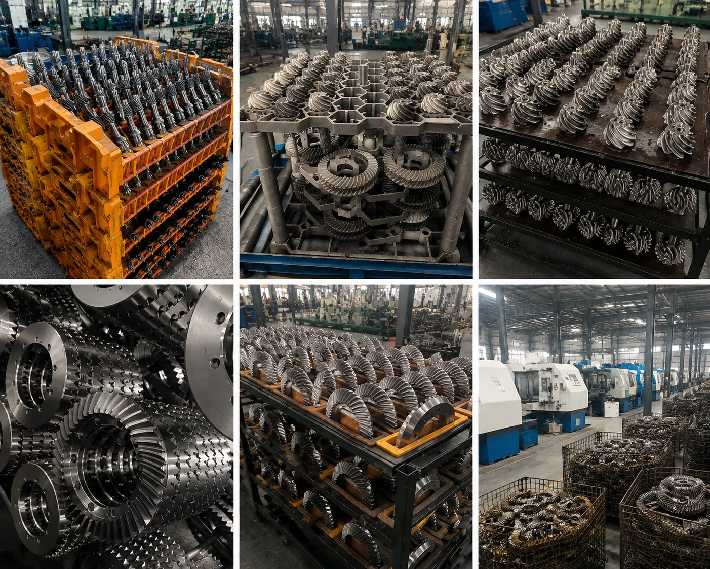
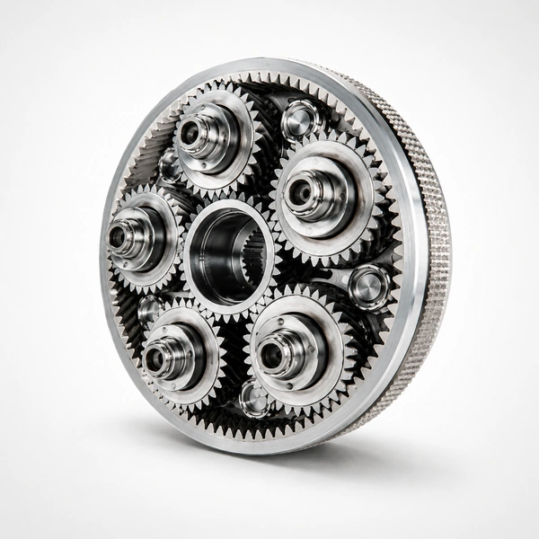
Korea Ever-Power’s helical gears for industrial gearboxes are manufactured in 20CrMnTi, 18CrNiMo7, and 42CrMo4 alloy steel to DIN 5–8 quality class, covering single-stage gearbox applications from 2.2 kW to multi-stage industrial gearboxes above 5,000 kW. All helical gears for enclosed gearbox applications are finish-ground after case hardening to achieve the tooth profile and lead accuracy that determines gearbox noise at operating speed.
The higher total contact ratio of helical gears (typically 1.5–2.5 vs 1.2–1.6 for spur gears at the same module) means more teeth share the transmitted load at any instant, reducing the peak bending stress at each tooth root and the peak Hertzian contact stress at each tooth flank. This dual improvement in both bending and contact stress allows helical gearboxes to transmit the same power as an equivalent spur gearbox in a smaller centre distance — or to transmit significantly more power within the same gearbox housing envelope.
Progressive Tooth Engagement
Helical tooth contact begins at one end and sweeps diagonally across the face — contact line length grows progressively from zero to maximum, then reduces back to zero. This eliminates the abrupt load onset of spur gears. The result is lower dynamic mesh force, lower vibration transmission to the gearbox housing, and dramatically reduced airborne gear mesh noise at all gearbox operating speeds.
Higher Load Capacity per Centre Distance
The higher total contact ratio of helical gears allows the same transmitted torque to be shared across more simultaneous tooth contacts, reducing peak root stress and flank contact stress relative to spur gears at the same module and face width. In practice, helical gearboxes achieve 15–30% higher power density than spur gearboxes of equal housing dimensions — a critical advantage in space-constrained industrial gearbox installations.
Smooth Torque Transmission
Helical gear transmission error — the deviation from perfectly uniform angular velocity ratio — is lower than spur gears at the same DIN quality class because the overlap ratio buffers individual tooth spacing errors across multiple simultaneous contacts. Low transmission error means smooth output shaft rotation, which is critical for gearbox applications driving precision machinery, machine tools, and servo-controlled systems where torque ripple must be minimised.
Helix Angle Selection: Noise, Thrust and Face Width
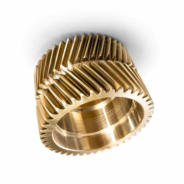
Helix angle is the most important design variable in helical gearbox design after module and gear ratio. It directly controls the balance between three competing effects: noise reduction (higher helix angle = lower noise), axial thrust generation (higher helix angle = higher thrust load on shaft bearings), and minimum face width requirement (higher helix angle = wider face required for one full tooth to span the face width — the overlap ratio >1.0 condition for smooth operation).
AXIAL THRUST MANAGEMENT IN SINGLE-HELICAL GEARBOXES
Thrust Magnitude
Fa = Ft × tan(ψ) where Ft is the tangential force and ψ is the helix angle. At ψ = 20° and 15 kW at 1,000 RPM: Ft = 9,550 N; Fa = 9,550 × tan(20°) = 3,475 N. This axial thrust must be reacted by angular contact or tapered roller bearings on both shaft ends.
Bearing Selection
Single-helical gearbox shafts require bearings capable of carrying both radial and axial load simultaneously. Angular contact ball bearings (15° or 25° contact angle) handle moderate axial thrust; tapered roller bearings handle heavy thrust at low speed; paired cylindrical + thrust bearing arrangements separate the radial and axial load paths for high-speed precision gearboxes.
Double Helical Solution
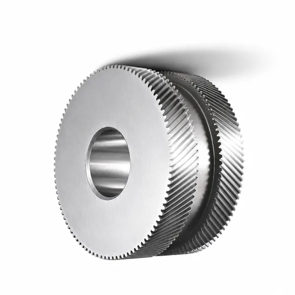
Double helical (herringbone) gears use opposing left-hand and right-hand helices on the same gear body — the axial thrust from each helix exactly cancels, producing zero net axial force. This allows helix angles of 25°–35° for maximum noise reduction without imposing axial thrust on bearings. Required: a floating shaft arrangement to allow self-equalization of both helix loads.
Material and Heat Treatment for Industrial Gearbox Helical Gears
20CrMnTi — Case Carburized
Standard for industrial gearbox helical gears requiring maximum fatigue life. Case depth 0.8–1.5 mm, HRC 58–62 tooth surface, σF = 380–430 MPa, σH = 1,400–1,550 MPa. After carburizing and quenching, profile and lead grinding to DIN 5–6 compensates for heat treatment distortion and achieves the accuracy required for low-noise gearbox operation above 5 m/s pitch line velocity.
✓ Standard for PLV > 5 m/s gearbox
18CrNiMo7-6 — High Power
Premium case-carburizing steel for high-power and high-cycle industrial gearboxes — wind turbine main gearboxes, marine reduction gearboxes, and steel mill drives. Higher Ni content (1.4–1.7%) gives superior core impact toughness (AKV > 80 J at −20°C) for gearboxes subject to shock loading. σF = 430–480 MPa. Specified in ISO 6336 and AGMA 2101 high-reliability calculations. Case depth 1.0–2.0 mm for large-module gears.
✓ Wind turbine, marine, steel mill gearbox
42CrMo4 — Through-Hardened
Through-hardened and tempered to HB 280–340 for medium-duty gearbox helical gears where case carburization cost is not justified by the application duty. σF = 260–310 MPa, σH = 1,000–1,150 MPa. No post-hardening grinding required — the uniform hardness profile means minimal distortion during heat treatment. Hobbed to DIN 7–8 for gearboxes at PLV below 5 m/s. Lower cost than case-carburized option for medium-duty industrial gearboxes.
✓ Medium-duty gearbox, PLV < 5 m/s
Stainless / Food-Grade
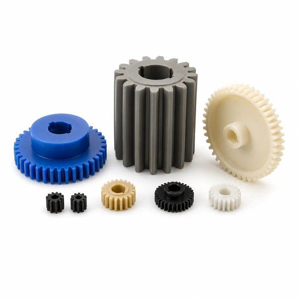
316L or 17-4 PH stainless steel for food processing gearboxes and chemical plant gearboxes subject to corrosive washdown. Lower allowable stresses than alloy steel (σF = 130–200 MPa) require larger module or wider face width for equivalent power. Paired with plastic gears in mixed material gearbox stages for food-contact compliance without full stainless gearbox cost.
✓ Food, pharma, chemical plant gearbox
Industrial Gearbox Applications by Sector
Frequently Asked Questions
Explore Korea Ever-Power Gear Categories
Seven precision gear product lines for industrial, automotive, agricultural and specialist applications worldwide.
Redattore: Cxm
 Italian
  English
  Korean
  French
  Japanese