GEAR APPLICATION GUIDE · BEVEL GEAR · B09

Bevel Gears for Robotics and Automation:
Wrist Drives, Angular Joints and Collaborative Robot Direction Change

Bevel gears in robotics and automation fill a design role that no other gear type can replace — they redirect shaft rotation through a defined angle (most commonly 90°) in a compact package that integrates directly into the robot joint or gripper actuator mechanism, enabling the perpendicular wrist roll and tool-change axes that give multi-axis robots their spatial dexterity. Unlike the spur and helical gears that handle the high-ratio reduction in robot joint drives, the bevel gear in a robot application is typically used at a ratio of 1:1 to 3:1, making it a direction-change element rather than a speed-reduction element. This guide covers bevel gear application in 6-axis robot wrist drives, linear motion robot end effectors, parallel kinematic robot (delta robot) arm angle joints, and precision CNC machine tool automatic tool changer (ATC) mechanisms that share the same precision requirements as robotic systems.

20CrMnTi · 17-4 PH · PEEK · M1–M4 · DIN 5–7
Ratio 1:1–3:1 · Backlash ≤ 2 arc-min · 100M cycles
Wrist · Delta · SCARA · ATC · Cobot

MODULE RANGE

M1 – M4

Robotic bevel gear module range. Robot wrist micro-actuator: M1–M1.5. 6-axis robot wrist J4–J6: M1.5–M2.5. Collaborative robot elbow angle joint: M2–M3. CNC ATC and delta robot arm: M2–M4. All require spiral bevel tooth form above M2 and DIN 5–6 profile ground for low noise and backlash control

TOOTH FORM

Spiral Bevel

Spiral bevel is the standard tooth form for all robotic bevel gears at PLV above 2 m/s or where noise below 65 dB(A) is required. Straight bevel is acceptable for the slowest joints (below 1 m/s PLV) and for cost-sensitive cobot auxiliary drives. Spiral bevel provides 30–40% higher load capacity and significantly lower noise than equivalent straight bevel at robot wrist speeds

BACKLASH

≤ 2 arc-min

Maximum backlash for robotic spiral bevel gear pairs. Robot wrist J6 (tool rotation): ≤ 1 arc-min. J4–J5 wrist pitch/roll: ≤ 2 arc-min. Collaborative robot angle joints: ≤ 3 arc-min. ATC and tool change mechanisms: ≤ 5 arc-min (ATC does not require the same positioning precision as a robot joint)

MATERIAL

20CrMnTi / 17-4 PH

Standard robotic bevel: 20CrMnTi case carburized, profile ground. Medical, food, cleanroom: 17-4 PH precipitation hardened (H900 condition, HRC 38–43) — corrosion-resistant, autoclave-compatible, sterilisable. PEEK spiral bevel available for food and pharmaceutical cobots at light duty below 15 Nm output torque

Bevel Gear Engineering for Robotic Applications — Precision Direction Change

The role of bevel gears in robotic and automation systems is fundamentally different from their role in industrial machinery. In a standard industrial application (a conveyor right-angle drive, an agricultural implement drive), the bevel gear pair is a direction-change element between two shafts that are fixed in space — the alignment between the bevel gear pair is set once at installation and does not change during operation. In a robotic application, the bevel gear pair in a wrist joint is part of a kinematic chain where every upstream joint rotation changes the spatial orientation of the bevel gear pair — the J4 wrist bevel gear pair, for example, rotates its own axis with every J1, J2, and J3 movement, carrying dynamic loads from acceleration and deceleration that are not present in a fixed-installation bevel drive. This kinematic coupling of the bevel gear load with the robot’s full motion profile makes the dynamic load analysis of robotic bevel gears significantly more complex than standard industrial bevel gear design.

Korea Ever-Power’s bevel gears for robotics and automation are manufactured in 20CrMnTi case carburized for the standard industrial and collaborative robot joint market, and in 17-4 PH stainless (H900, HRC 38–43) for all food, pharmaceutical, cleanroom, and medical robotic applications. The spiral bevel tooth form is standard for all robotic bevel gears at M1.5 and above — the overlapping tooth contact of the spiral form provides 30–40% higher load capacity at the same pitch diameter and smoother torque transmission with lower dynamic mesh force than straight bevel. For the very smallest robotic bevel gears at M1 module (used in surgical robot end-effectors and micro-gripper actuators), straight bevel is used because the spiral bevel geometry at M1 is too fine for reliable manufacturing by the Gleason face-milling process — Korea Ever-Power uses the Klingelnberg cyclo-palloid spiral bevel process for M1–M1.5, which is capable of generating accurate spiral bevel geometry at smaller modules than the standard Gleason process.

The backlash control of robotic bevel gears is achieved through the combination of tight manufacturing tolerances on the tooth thickness and the adjustable mounting distance (V-distance) of the bevel gear pair — the same principle as for standard miter gears, but applied with much tighter tolerances. The V-distance adjustment in a robot wrist bevel gear pair is typically accomplished by shimming the inner bearing of each shaft — a stack of thin shims between the bearing outer race and the housing bore that controls the axial position of each gear to within ±0.01 mm. Korea Ever-Power supplies robotic spiral bevel gear pairs with the measured tooth thickness of each gear (to ±0.002 mm, measured by an over-pin method with a calibrated micrometer), the tooth contact pattern photographs at 25%, 50%, and 75% of rated torque, and the calculated V-distance adjustment required to achieve the target backlash. This documentation package allows the robot builder to achieve the target backlash at first assembly without iterative trial-and-error shimming — a significant time saving in high-volume robot production.
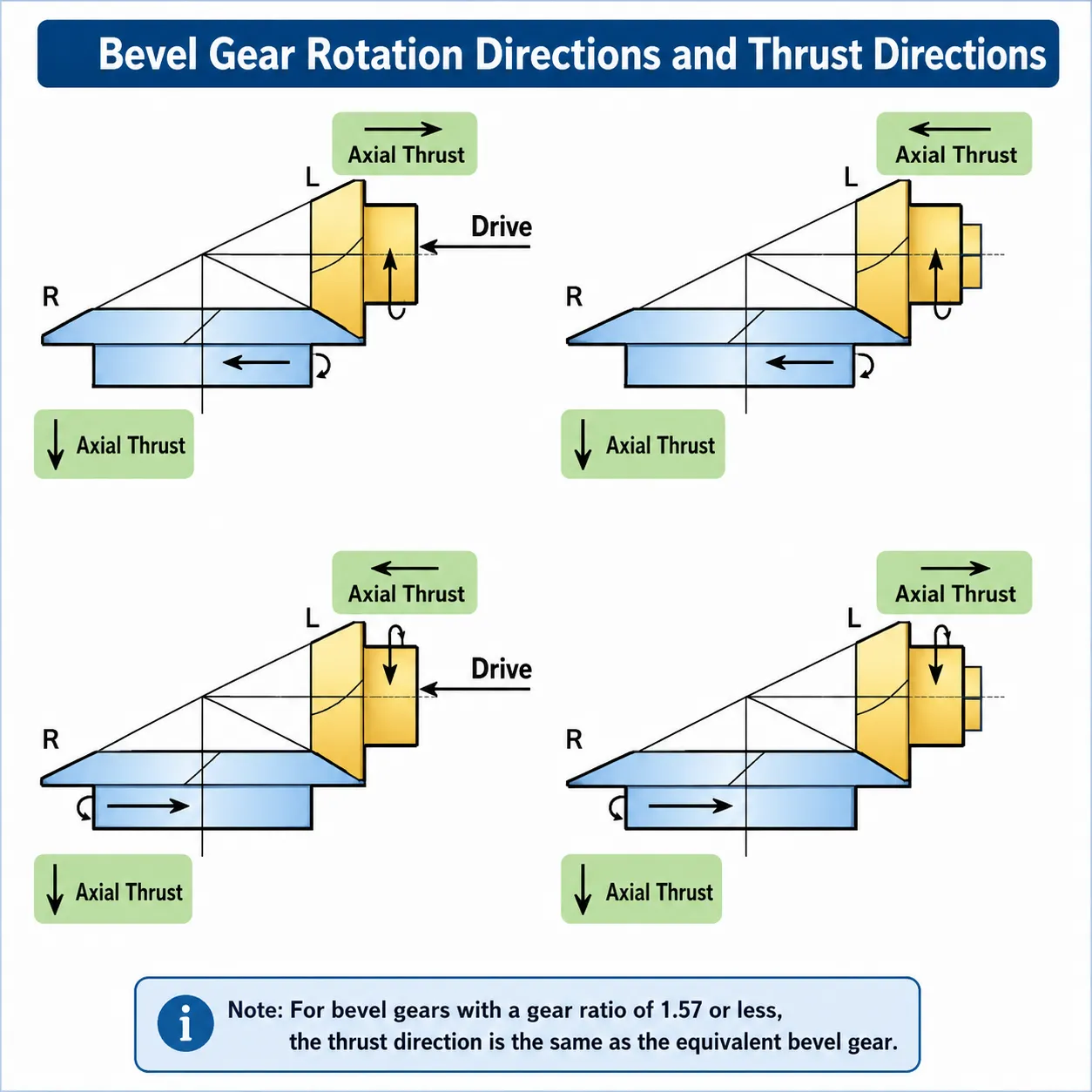
bevel gear rotation thrust direction robotics Korea Ever-Power
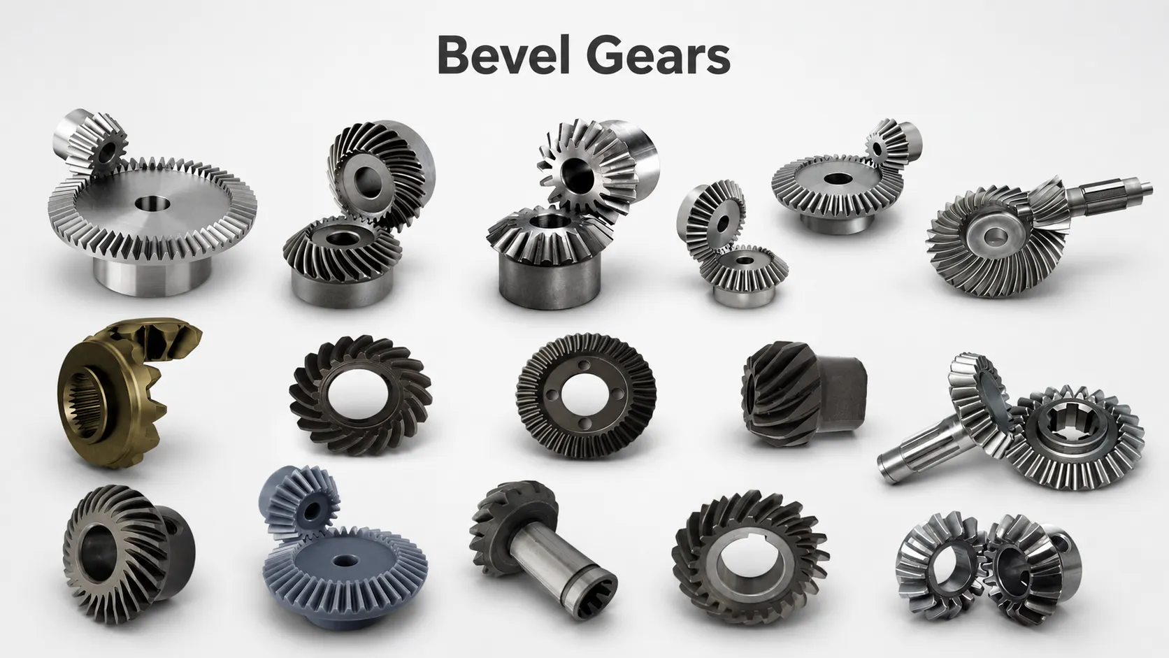
Korea Ever-Power bevel gear rotation direction and axial thrust direction reference for robotic wrist joint design — spiral bevel pair M2, 20T each (1:1 miter configuration), 20CrMnTi carburized HRC 60–62. The axial thrust direction produced by a spiral bevel gear (dependent on the hand of spiral and rotation direction) is a critical design parameter for robotic wrist joints — the thrust load must act in the direction that seats the bearing against its housing shoulder (not lifts it away), otherwise the bearing preload reduces to zero and radial play develops in the joint. Korea Ever-Power documents the axial thrust direction for every robotic spiral bevel gear pair (as a function of the spiral hand, rotation direction, and which gear is driving) on the product datasheet, enabling the robot structural engineer to confirm the bearing configuration before ordering. All Korea Ever-Power robotic bevel gears are supplied in matched pairs from the same manufacturing batch to ensure tooth contact pattern compatibility.

Robot Application Bevel Gear Specifications

6-Axis Robot Wrist (J4–J6)

M1.5–M2.5 spiral bevel, 20CrMnTi carburized, DIN 5–6 ground, individually matched pair from same production run. The J4, J5, and J6 wrist joints of a 6-axis industrial robot are the axes most commonly incorporating bevel gears — they enable the compact, spherical wrist configuration that allows the robot tool to reach any orientation. J6 (tool rotation) is typically a spur gear driven wrist, but J4 and J5 often use bevel pairs for the space-efficient 90° direction change within the wrist housing. The bevel gear in a robot wrist runs at the highest speed of any joint (J6 can reach 500–900 RPM output), placing the pitch line velocity of M2 bevel gears at 1.5–3 m/s — requiring spiral bevel for smooth, low-noise operation. Temperature limit for the wrist joint: 60–80°C continuous, 100°C peak — standard greases remain within specification at these temperatures, but Korea Ever-Power provides high-temperature-rated gear greases for robot manufacturers whose wrist joints exceed 80°C in automotive welding or plasma-cutting environments.

M1.5–M2.5 · spiral · DIN 5–6 · 20CrMnTi

Delta Robot Arm Joint

M2–M4 spiral or straight bevel, 20CrMnTi or C45 induction hardened, DIN 6–7, 1:1 ratio (miter configuration common), high fatigue cycle life mandatory (>500 million). Delta robots (parallel kinematic architecture, used in food packing, pharmaceutical sorting, and electronics assembly for high-speed pick-and-place) use bevel gears in the forearm link angle joints that transmit the end-effector rotation (J4 rotation) down through the parallel arms to the tool. These bevel gears operate at the high cycle rates characteristic of delta robot pick-and-place operation — 120–200 cycles per minute in food packing applications, accumulating 500+ million cycles per year. The load on delta robot arm bevel gears is primarily from the end-effector inertia during rapid acceleration and deceleration at cycle reversal — the dynamic load at the bevel gear tooth can be 3–5× the static load at the rated end-effector mass. Korea Ever-Power delta robot bevel gears are designed with a dynamic load factor K_v = 1.5 to account for these impulse loads at reversal, in addition to the fatigue life calculation for the mean load.

M2–M4 · spiral · DIN 6–7 · high cycle fatigue

CNC ATC Mechanism

M2–M4 spiral bevel, C45 induction hardened or 20CrMnTi carburized, DIN 6–7, toolchanger-speed rated (up to 3 m/s PLV for fast ATC designs), compact housing integration. CNC machining centre automatic tool changers (ATCs) use bevel gears in the tool pot carousel drive, the arm swing mechanism, and the tool clamp/release actuator angle joints — all of which require compact right-angle drives that fit within the tight spatial envelope of the tool changer magazine and arm. The ATC bevel gear operates at lower precision requirement than a robot joint (the tool position is ultimately determined by the spindle taper, not the ATC gear position), but at high cycle rates — a machining cell running 500 tool changes per shift accumulates 1 million tool change cycles per year. Korea Ever-Power ATC bevel gears for Fanuc, Mazak, Yamazaki, and DMG Mori machining centres are supplied in M2–M4 with DIN 6–7 quality and C45 or 20CrMnTi material matching the original ATC mechanism specification.

M2–M4 · ATC magazine · DIN 6–7 · compact
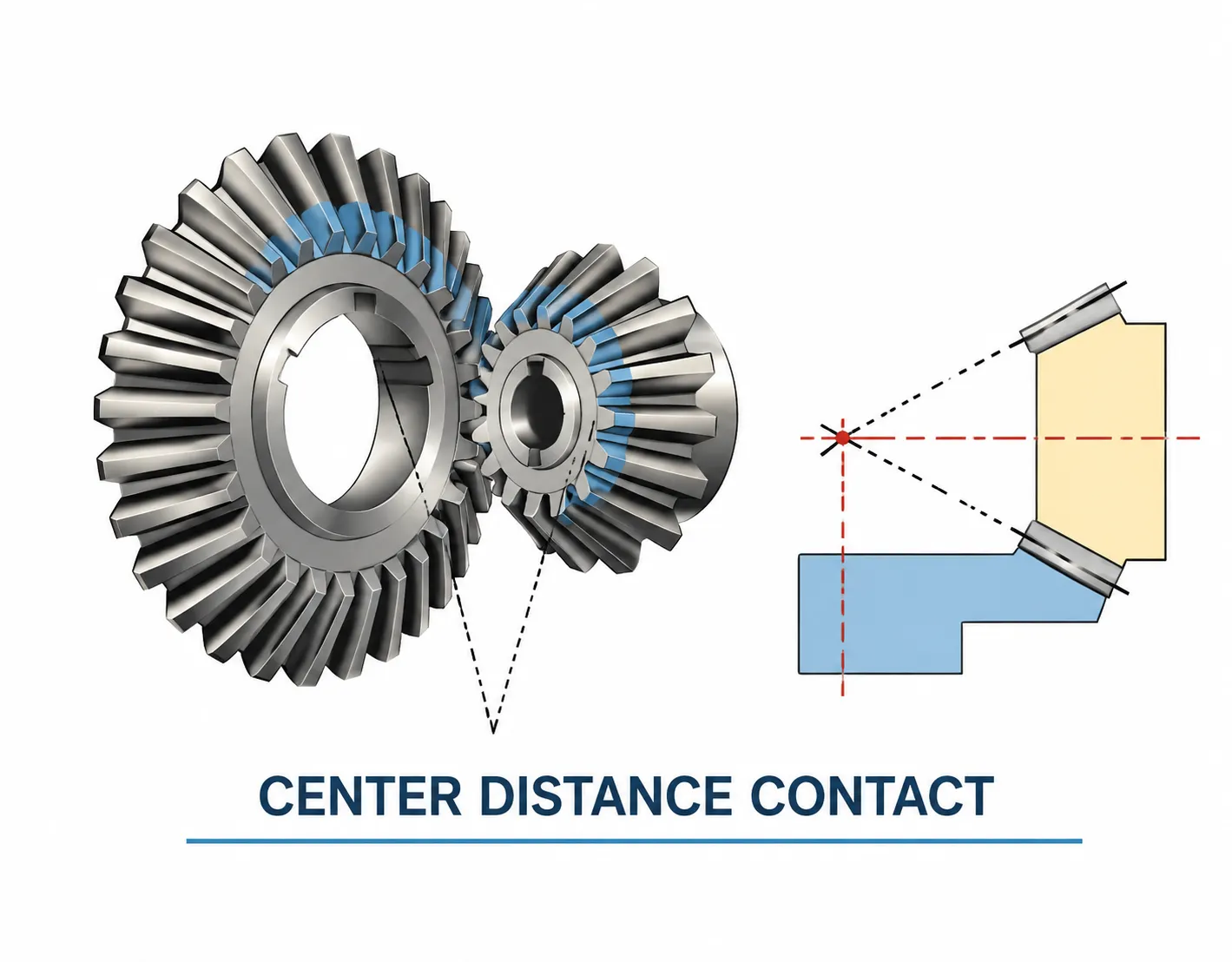
bevel gear contact pattern robotics precision Korea Ever-Power
Korea Ever-Power robotic spiral bevel gear contact pattern verification — blue marking applied to the wheel tooth, pair assembled at the target mounting distance V and loaded to 50% rated torque. The contact pattern shows the contact ellipse centred in the mid-zone of the tooth face (approximately 50–60% of the face width from the heel), with adequate clearance from both the toe and heel edges. The contact ellipse shifts toward the heel at full rated torque as the housing deflects under load — this shift is designed in by the spiral bevel tooth geometry (positive face curvature in the Gleason system) so that full-load contact remains within the tooth face without edge loading. Korea Ever-Power includes three contact pattern photographs (at 25%, 50%, and 75% of rated torque) with every robotic bevel gear pair order above M2, enabling the robot joint designer to confirm the contact quality before series production assembly begins.
Korea Ever-Power precision manufacturing robot bevel gear spiral bevel production
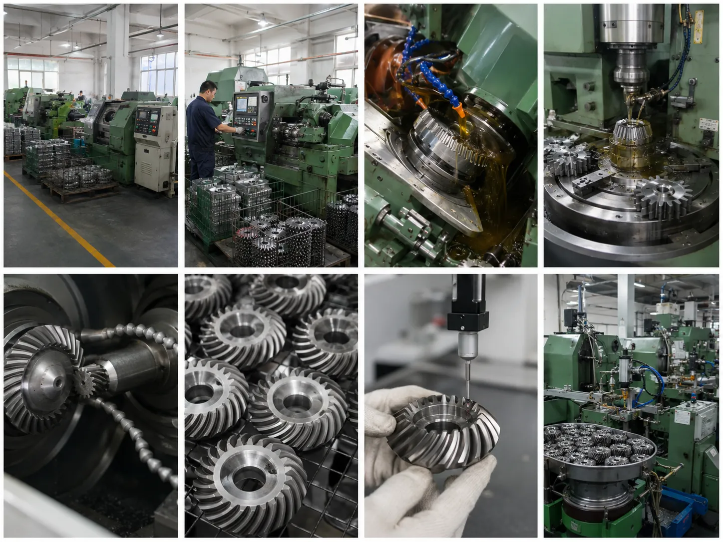
Korea Ever-Power precision manufacturing facility for robotic spiral bevel gears — Gleason CNC spiral bevel cutting and Klingelnberg cyclo-palloid grinding for M1–M4 robot joint bevel gears. The robotic bevel gear production process requires significantly tighter process control than standard industrial bevel gear manufacture: each spiral bevel pair is individually lapped for 30–60 minutes at 25% rated torque after grinding to confirm and document the contact pattern, compared to the sampling-based contact check used for standard industrial bevel production. The individual lapping step adds 15–20 minutes per pair to the production cycle time but ensures the contact pattern of every pair shipped to a robot OEM customer is within the specified quality level — critical for robot OEM assembly lines where a single gear pair with incorrect contact pattern would require the robot joint to be disassembled after NVH testing, a costly rework operation in automated robot assembly.

Frequently Asked Questions — Bevel Gears for Robotics and Automation

Q 01

When should I specify spiral bevel vs straight bevel for a robotic angle drive? Are there cost or performance tradeoffs I need to be aware of?

The specification decision between spiral bevel and straight bevel for a robotic angle drive is primarily determined by three factors — pitch line velocity, noise requirement, and load capacity — with the cost premium for spiral bevel approximately 40–70% over equivalent straight bevel at the same module and size. Pitch line velocity: above 2 m/s (at the pitch circle), straight bevel gears produce an audible impact noise at each tooth entry — the “whine” that characterises high-speed straight bevel drives. For a robot wrist joint running at 400 RPM with an M2 bevel gear (pitch diameter ≈ 40 mm), PLV = π × 0.040 × 400/60 = 0.84 m/s — below the 2 m/s threshold. Straight bevel is acceptable here. At 1,000 RPM with the same gear: PLV = 2.1 m/s — spiral bevel required. Noise requirement: for collaborative robots working near human operators and for robots in office or laboratory environments, the 65 dB(A) ambient noise target drives the gear noise requirement below what straight bevel can achieve at any speed. Spiral bevel typically produces 5–8 dB(A) less noise than straight bevel at the same PLV and load. Load capacity: spiral bevel has 30–40% higher load capacity at the same module because the face contact ratio from the spiral tooth overlap is higher. If the straight bevel design is operating at more than 75% of its rated load, the spiral bevel upgrade is likely to extend gear life significantly. Cost-justified specification rule: for robot joint output torques above 15 Nm at any speed, specify spiral bevel. For below 15 Nm and below 500 RPM at the bevel gear: straight bevel is acceptable and reduces component cost.

Q 02

Our 6-axis welding robot’s J5 wrist joint is producing a knocking noise at high speed during path interpolation. We’ve confirmed the bevel gears are worn. How should we specify the replacement pair to eliminate the noise?

A knocking noise from the J5 wrist bevel gears during high-speed path interpolation is typically the sound of impact at the bevel gear tooth entry caused by one or more of: (1) Worn tooth profile causing increased transmission error: as the spiral bevel tooth flanks wear, the carefully designed contact ellipse (which provides a smooth, progressive load transfer from tooth to tooth) degrades to an irregular point contact at the worn areas, generating an impulse at each tooth mesh. The impulse frequency equals the tooth mesh frequency (RPM × tooth count / 60) — at 600 RPM J5 speed and 20-tooth bevel gear, this is 200 Hz, well within the audible range. (2) Increased backlash from wear: the worn tooth flanks produce a larger backlash dead-band, causing the gear to impact across the gap at each direction reversal during path interpolation. The reversal impact noise is typically lower in frequency and higher in amplitude than the mesh frequency knock. Replacement specification to eliminate the noise: (a) Specify 20CrMnTi carburized (if original was C45 — a common OEM cost-reduction specification) for 3× longer tooth flank fatigue life. (b) Upgrade from DIN 7 to DIN 6 profile ground — the tighter DIN 6 profile tolerance produces a contact ellipse that remains in the designed tooth zone over a wider range of manufacturing variation, reducing the sensitivity to minor housing deflection and bearing clearance that shifts the contact toward the edge. (c) Apply 3 μm tip relief on both gears — the tip relief smooths the load transfer at tooth entry and exit, reducing the impulse amplitude by 30–40%. (d) Confirm the J5 wrist housing bearing preload at the same time — worn bearings allow the bevel gear pair to shift out of the designed V-distance and alter the contact pattern, contributing to the noise. Submit the J5 wrist housing bore diameter and bearing specifications with the gear order for Korea Ever-Power to calculate the required shim adjustment for target backlash at first assembly.

Q 03

What is Korea Ever-Power’s capability for supplying bevel gears to robot OEM manufacturers in volume production quantities — say 5,000 pairs per year?

Korea Ever-Power supplies bevel gears to robot OEM manufacturers in volume production quantities under long-term supply agreements. Our OEM bevel gear supply capability for robotic applications: (1) Annual capacity: 50,000–150,000 spiral bevel gear pairs per year in the M1–M4 module range for robotic applications, from a dedicated CNC bevel gear cutting and grinding production cell. 5,000 pairs/year is well within the standard production capacity without dedicated tooling investment. (2) Quality consistency in volume production: we use first-article inspection (FAI) for each new robot model — a full dimensional, material, and contact pattern inspection of 5 pairs from the first production batch, with the robot OEM’s quality team reviewing the FAI report before production release. In series production, we apply statistical process control (SPC) on the critical measurements: tooth thickness (±0.003 mm), helix angle (±0.008°), and contact pattern (photo documentation on 5% of pairs). (3) Traceability: all production batches are traceable to the steel melt heat and gear grinding machine record, retained for 5 years — meeting ISO 9001:2015 clause 8.5.2 traceability requirements. (4) Delivery cadence: volume supply agreements run on a 6-week forecast pull system — the OEM issues a 6-week forecast monthly, and Korea Ever-Power ships the forecast quantity in weekly or bi-weekly lots. Lead time on forecast quantity: 7 days from dispatch notification. Lead time on out-of-forecast quantities: 15–20 days. Volume pricing for 5,000 pairs/year provides a 20–30% reduction from the single-order catalogue price for the same specification. Contact Korea Ever-Power with the robot model, joint location, gear specification (module, tooth count, material, quality class), and forecast annual volume for an OEM supply agreement proposal.

Explore Korea Ever-Power Gear Categories

Seven precision gear product lines for robotics, automation, CNC machining and precision industrial applications worldwide.
spur gear robot

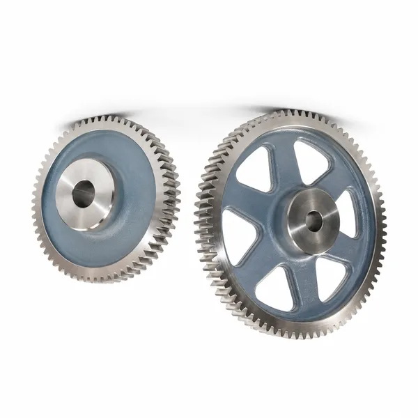
Spur Gears

DIN 4–6 · robot joint · low backlash

helical gear robot

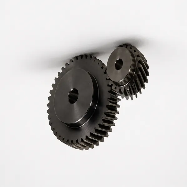
Helical Gears

Robot pre-stage · gearbox · low TE

bevel gear robot wrist

Ingranaggi conici

Spiral bevel · wrist · ATC · M1–M4

worm gear

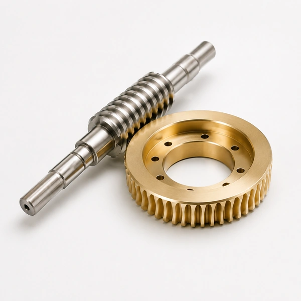
Worm Gears

Robot base · self-locking · slow axis

ring gear robot

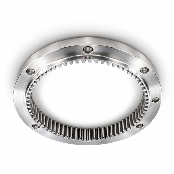
Ring Gears

Harmonic · planetary · robot joint

planetary gear robot

Planetary Gears

Compact · servo · robot stage kit

plastic gear robot

Plastic Gears

PEEK · cobot · food-grade · dry

GET A QUOTATION · KOREA EVER-POWER

Need Bevel Gears for Robotics and Automation?

Korea Ever-Power manufactures 20CrMnTi, 17-4 PH stainless, and PEEK spiral bevel and straight bevel gears for all robotic and automation applications — M1–M4, DIN 5–7, backlash documentation, contact pattern photos at 3 load levels, V-distance shim calculation. Applications: 6-axis wrist J4–J6, SCARA arm, delta robot, CNC ATC, surgical robot. Volume OEM supply from 500 to 150,000 pairs/year. ISO 9001:2015 certified.

Request a Quotation →

Redattore: Cxm

VR Tour of Our Factory

TAGs:

cremagliera degli ingranaggi

In qualità di uno dei principali produttori, fornitori ed esportatori di cremagliere, offriamo cremagliere e molti altri prodotti.

Vi preghiamo di contattarci per maggiori dettagli.

Posta:[email protected]

Produttore, fornitore ed esportatore di cremagliere

Articoli recenti

it_ITItalian