
Helical Gears for Crane and Hoist Drives:
Overhead Cranes, Port Hoists and Industrial Lifting Equipment
Crane and hoist helical gears operate under a duty cycle that is unique among industrial gear applications — the torque is applied in discrete, often unpredictable intervals (each lift event), with significant shock loading at the moment of load pickup when the rope suddenly tensions against a stationary or slowly moving load, and the consequence of gear failure is the risk of an uncontrolled load drop — a safety outcome that is unacceptable under any design condition. This guide covers helical gear specification, duty cycle analysis, safety factor selection, and material requirements for overhead travelling cranes, jib cranes, port container cranes, and industrial hoist units from 1 tonne through 500 tonne lifting capacity.
SF 1.5–2.5 · DIN 5–7 · Load Spectrum · ISO 4301
Overhead · Port · Jib Crane · Industrial Hoist
Crane Hoist Helical Gear Engineering — Duty Class, Load Spectrum, and Safety Requirements
The engineering of helical gears for crane and hoist drives cannot be reduced to a simple calculation of the rated lift torque divided by a service factor — the crane gear duty is fundamentally a stochastic (probabilistic) problem, where the gear experiences a statistical distribution of loads across a range from zero (hook running empty) to the rated maximum lift load, with the distribution depending on the crane’s service conditions. A warehouse crane that primarily lifts palletised goods at 80–100% of its rated capacity has a very different load spectrum from a scrap-handling crane that lifts electromagnet grabs at 20–30% of rated capacity most of the time but occasionally lifts a full grab of heavy scrap at 100% rated. Both cranes may have the same rated lift capacity, but the scrap crane accumulates far fewer high-load fatigue cycles and could potentially use lighter helical gears for the same design life — or conversely the warehouse crane needs heavier gears despite the same rating.
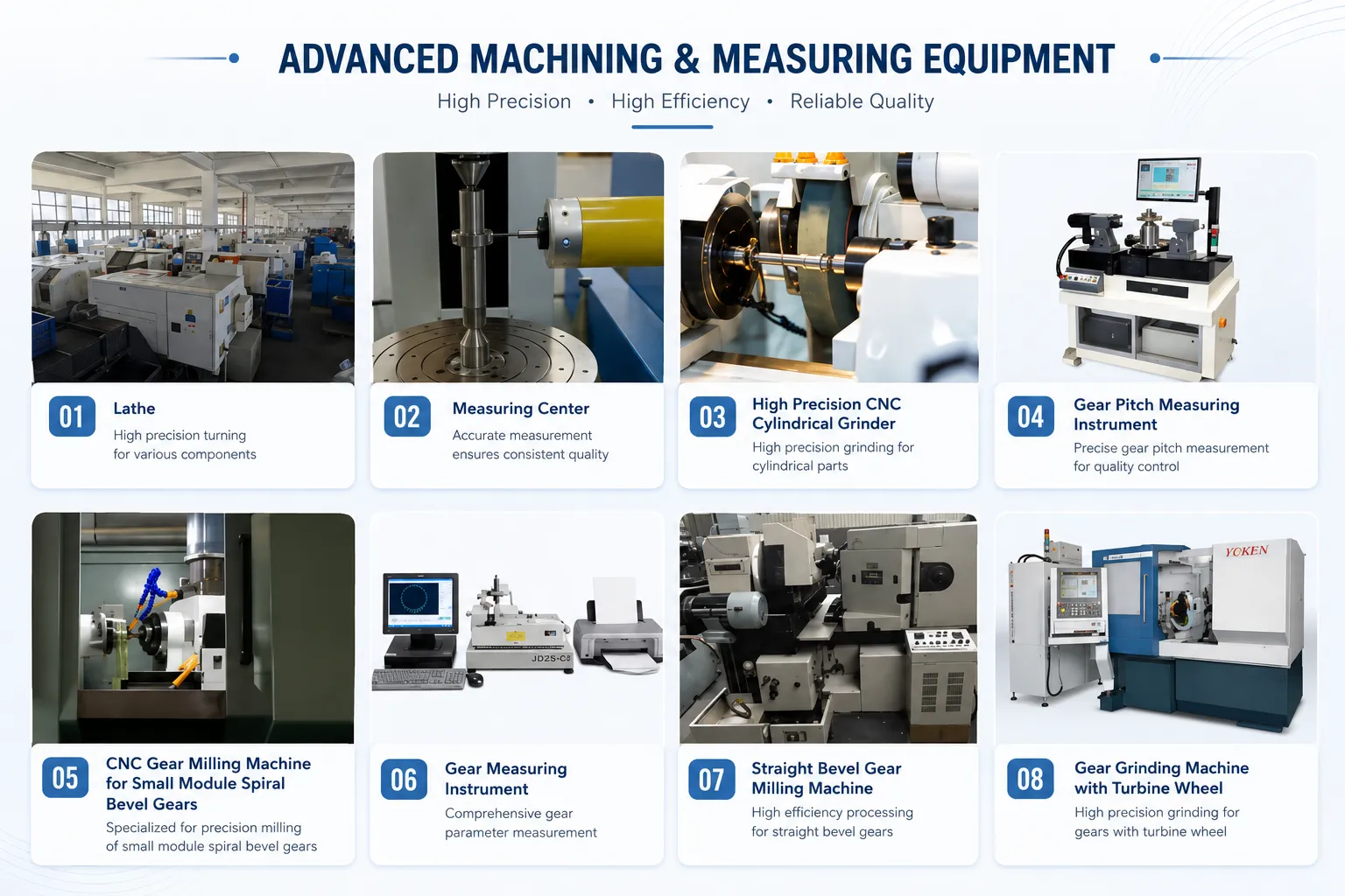
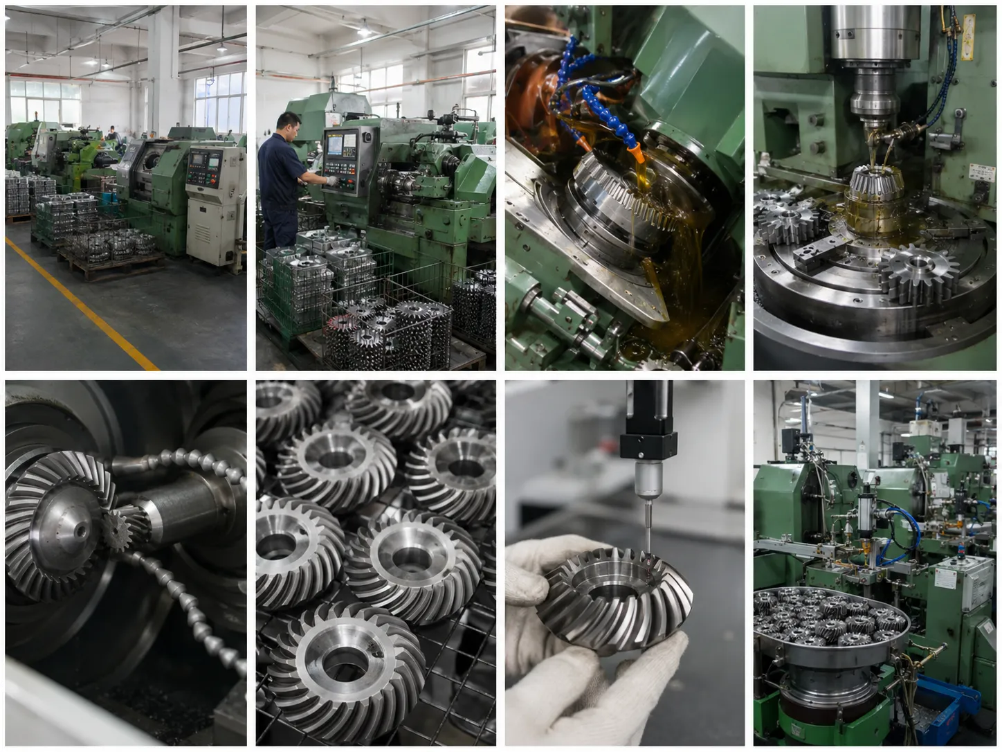
Korea Ever-Power’s helical gears for crane hoist drives are manufactured in 18CrNiMo7-6 case carburized (for heavy and extra-heavy duty M5–M8 cranes where maximum tooth bending and contact fatigue resistance is required) and 42CrMo4 through-hardened QT (for light and medium duty M3–M5 workshop crane hoists where the fatigue loading is within the capability of through-hardened steel). All crane hoist helical gears are subjected to 100% magnetic particle inspection (MPI) of all tooth surfaces and roots after final heat treatment and machining — a requirement of EN 13157 (European crane safety standard) that ensures any heat treatment cracks, grinding burns, or material defects are detected before the gear enters service. Korea Ever-Power provides MPI inspection certificates with every crane hoist helical gear shipment.
The shock loading at the moment of load pickup — when the lifting rope transitions from slack (or moving slowly downward) to suddenly taking the full weight of the suspended load — generates a dynamic torque spike in the hoist gearbox that is typically 1.5–3.0× the static lift torque, depending on the crane control system and the load pickup speed. Modern crane control systems with soft-start torque ramping reduce this spike to 1.5–2.0× static, but older direct-on-line or two-speed motor cranes may generate spikes of 2.5–3.0×. The helical gear service factor for crane hoist applications must account for this pickup torque spike as well as the nominal lift load fatigue — Korea Ever-Power uses the FEM crane gear design method (FEM 1.001, 3rd edition) to calculate the equivalent constant torque at the gear’s pitch point from the load spectrum and pickup shock factor, then applies this equivalent torque to the ISO 6336 fatigue calculation to determine the required module, face width, and material for the specified design life.
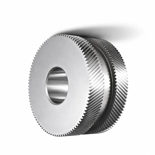
Crane Type Application Specifications
FEM Duty Class and Helical Gear Sizing — A Practical Guide
The FEM (Fédération Européenne de la Manutention, now FEM MHE) classification system for crane mechanisms provides a structured approach to helical gear design that properly accounts for the variable loading of crane operations — recognising that a crane hoist gear does not see its rated load on every lift. The FEM crane mechanism classification combines two parameters: the mechanism group (M1–M8, determined from the expected total number of working cycles over the crane’s design life) and the load spectrum class (L1–L4, determined from the proportion of lifts at rated load vs partial loads). The combination gives the mechanism class that directly determines the required fatigue life of the helical gear.
Frequently Asked Questions — Crane and Hoist Helical Gears
Explore Korea Ever-Power Gear Categories
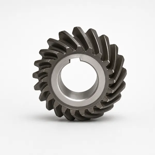
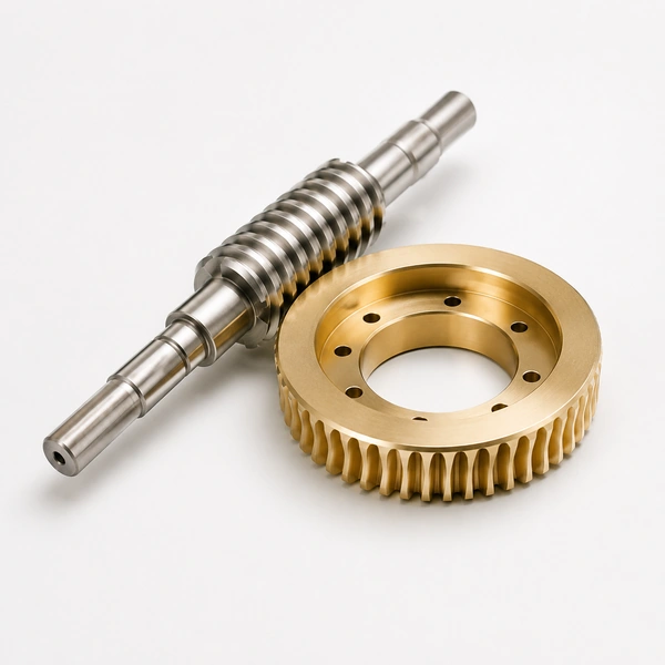
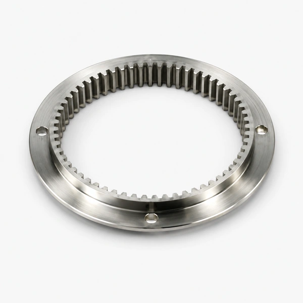
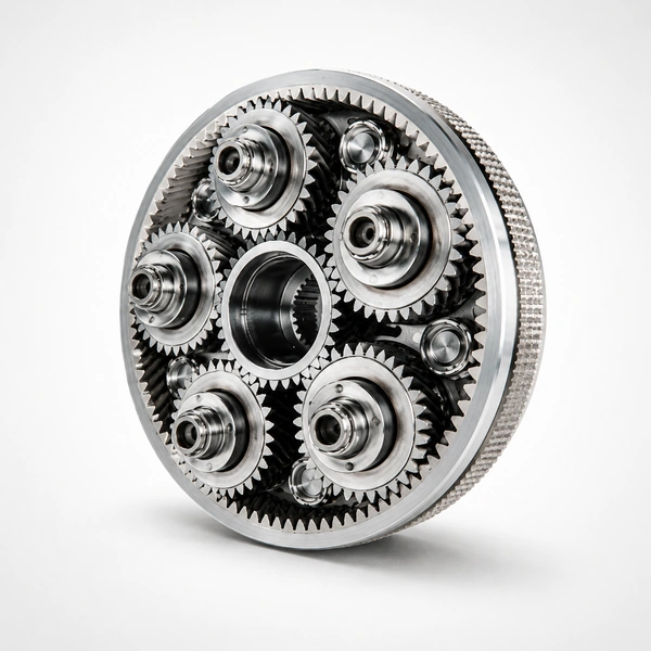
Seven precision gear product lines for crane, hoist, mining, industrial and port handling applications worldwide.
Redattore: Cxm
 Italian
  English
  Korean
  French
  Japanese