GEAR APPLICATION GUIDE · RING GEAR · R06

Ring Gears for Mining Machinery:
Ball Mill Drives, Rotary Kiln Rings and Large Diameter Mining Equipment

Mining machinery ring gears are the largest and heaviest gear components in any industrial application — the bull ring gear of a 36-foot diameter ball mill at an iron ore concentrator has an OD of 11 metres, weighs 80 tonnes, and is fabricated in segments that bolt together around the mill shell to form the complete ring. The forces transmitted through these gears are correspondingly massive: a 10 MW ball mill ring gear sustains tangential tooth loads of 800–1,200 kN at the pitch circle, while simultaneously being distorted and vibrated by the tumbling ore charge inside the mill that creates a fluctuating eccentric load on the shell and, through the shell, on the ring gear itself. Understanding and specifying ring gears for ball mills, rod mills, SAG mills, cement kilns, and large-diameter rotary dryers requires an engineering approach that combines standard gear fatigue analysis with the structural mechanics of large thin-ring deformation under eccentric load.

42CrMo4 · 34CrNiMo6 · Cast Steel · M20–M50
OD 1.5–12 m · DIN 8–10 · Segmented · 3–8 Segments
Ball Mill · SAG Mill · Rotary Kiln · Dryer · Cement

OD RANGE

1.5 – 12 m

Mining mill ring gear outer diameter range. Small pilot-scale mills: 1.5–3.0 m OD. Medium grinding mills (1–4 MW): 3–6 m OD. Large ball mills and SAG mills (4–12 MW): 6–10 m OD. Very large SAG mills (>12 MW): 10–12 m OD. Cement kiln main ring: 4–8 m OD. All above 3 m OD: segmented ring, 3–8 segments bolted at the mill shell flanges

MODULE RANGE

M20 – M50

Ball mill ring gear module range. Modules are large because the ring OD is large and the tooth count is moderate — typically 150–280 teeth on a ball mill ring. M20–M28: medium-sized mill rings (OD 3–6 m). M28–M40: large mill rings (OD 6–10 m). M40–M50: very large SAG mill rings (>10 m OD). These modules produce tooth heights of 45–112 mm — requiring specialised large-module gear hobbing or gear shaping machines

SEGMENTS

3 – 8 Segments

Ball mill ring gears above 3 m OD are fabricated in segments due to transportation and manufacturing constraints — the maximum size that can be transported by road without special permits is approximately 3.5 m OD × 4 m length. Typical segmentation: 2 halves (180° each) for OD 3–5 m; 3 segments (120° each) for OD 5–8 m; 4 or more segments for OD above 8 m. Segments are joined by high-strength bolts at machined-face flanges on the mill shell

MATERIAL

42CrMo4 / Cast Steel

Ball mill ring gear materials. Forged 42CrMo4 QT (HB 265–310): standard for medium and large mill rings where the forging can be produced. Cast steel G34CrNiMo6 (HB 240–280): used for very large ring segments (>10 tonnes per segment) where forging size is impractical. Cast steel allows more complex cross-section geometry and integrated bolt flanges than forging. All materials: tooth flanks induction or flame hardened after machining, or supplied in the QT condition for mills where the shock tolerance of unhardened teeth is preferred

Ball Mill Ring Gear Engineering — Large Module, Segmented Design and Eccentric Load

The ball mill ring gear presents engineering challenges that do not exist in any other ring gear application. The combination of very large module (M20–M50), segmented construction (which introduces load discontinuities at the segment joints), and eccentric loading from the tumbling charge inside the mill creates a gear loading situation that standard ISO 6336 calculations cannot fully capture without additional corrections for the ring flexibility and the dynamic load from mill charge movement. The eccentric load arises because the ball charge in a grinding mill does not rotate symmetrically about the mill axis — as the mill rotates, the charge cascades in a characteristic waterfall pattern that places the centre of gravity of the charge approximately 10–20° offset from the lowest point of the mill. This offset between the charge centre of gravity and the mill axis creates a dynamic overturning moment on the mill shell that is transmitted to the ring gear as a fluctuating pitch alignment error at the ring gear-pinion mesh — the tooth contact band shifts from side to side across the face width with each mill revolution, generating a variable face load distribution factor KHβ that is significantly higher than the static value calculated from the tooth stiffness alone.

Korea Ever-Power’s ring gears for mining machinery are manufactured in both forged 42CrMo4 (for rings up to approximately 8 m OD where the forging mass per segment is within practical forge capacity) and cast steel G34CrNiMo6 (for the largest rings above 8 m OD, or for rings with complex cross-section profiles that integrate the bolt flanges and stiffening ribs as cast features rather than as machined features from a forged blank). The tooth profile for mining mill ring gears is generated by gear hobbing or gear shaping with large-module tools — the hob for M30 gear teeth has a tooth height of 67 mm and requires a dedicated CNC gear hobbing machine with sufficient radial depth of cut capacity, which limits the manufacturers worldwide who can produce these gears. Korea Ever-Power has the large-module tooling and CNC gear cutting capacity to produce ring gear segments up to M50 module, OD 4 m per segment (equivalent to a 12 m OD complete ring in 3 segments).

The segment joint design is one of the most critical engineering aspects of a segmented ball mill ring gear — the joint must transmit the full tooth load across the discontinuity between segments without any relative movement between segment ends (which would cause fretting damage at the joint flanges and progressive loosening of the joint bolts). The standard approach is a precision-machined, flanged butt joint with high-strength bolts (grade 10.9 minimum), where the bolts are torqued to a preload that generates a clamping force significantly higher than the maximum tangential tooth force at the joint position. Korea Ever-Power designs the joint bolt preload based on the joint friction coefficient and the maximum tooth tangential force at the joint position, with a minimum safety factor of 1.5 on the no-slip condition — the joint must not slip under any normal operating load. All joint flanges are machined on the same vertical CNC boring machine as the ring gear tooth reference surfaces, ensuring the flange faces are parallel to the gear axis and perpendicular to the tooth pitch tangent at the joint position, which is critical for the correct alignment of the assembled ring gear.
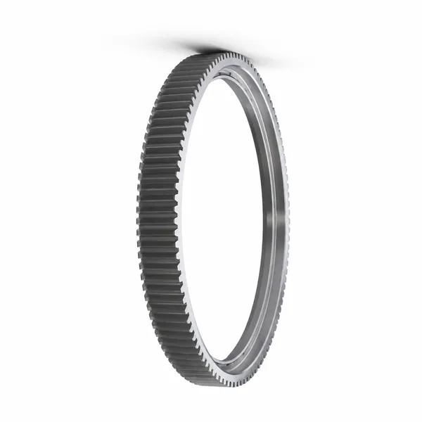
ring gear for mining mill cement kiln Korea Ever-Power large diameter
Korea Ever-Power large cast steel ring gear segment for cement mill and mining grinding mill application — M32, single segment (one half of a 2-segment ring assembly), approximately 150° arc, OD 5,400 mm, face width 640 mm, tooth count 84T per segment (168T assembled). G34CrNiMo6 cast steel, QT condition HB 260–290, tooth flanks flame hardened to HRC 48–54 after machining. The cast cross-section integrates the bolt flange (for attachment to the mill shell flange) and a circumferential stiffening rib at the ring centreline that improves the ring’s moment of inertia and reduces the tooth face load distribution change from ring distortion under the eccentric mill charge load. NDT of the casting: 100% UT volumetric inspection of the casting per EN 12680-1 Class 2 (no allowable discontinuities above 3 mm equivalent diameter in the tooth zone); MPI of all tooth flanks and root fillet areas after machining and after flame hardening. Tooth quality: DIN 9 (the maximum achievable quality on large segmented rings due to the thermal distortion from flame hardening and the difficulty of re-fixturing large segments for corrective grinding).

Mining Equipment Ring Gear Application Specifications

SAG and Ball Mill Ring Gears (3–12 m OD)

SAG (Semi-Autogenous Grinding) and ball mills are the primary size reduction equipment in hard rock mining — copper, gold, iron ore, and nickel processing plants use these mills to grind ore from run-of-mine size (150–200 mm) to the particle size required for flotation or magnetic separation (typically 75–150 μm). The ring gear is the power transmission interface between the pinion drive motor and the rotating mill shell — the ring gear runs at 10–20 RPM (the optimal mill rotation speed for grinding efficiency) driven by a pinion at the motor gearbox output at 50–100 RPM through a step-down ratio of approximately 3:1–6:1. Korea Ever-Power ball mill ring gears are designed with a minimum tooth bending fatigue life of 10⁷ cycles at rated tangential load — equivalent to approximately 10 years of continuous operation at typical mill rotation speeds. The very large module (M24–M36 for medium mills) means that each individual tooth contacts the pinion relatively infrequently per unit time, so the cumulative tooth cycle count over the design life is lower than for a high-speed gearbox despite the high transmitted power.

M24–M36 · OD 3–8 m · cast or forged segments · 10⁷ cycle life

Rotary Kiln Ring Gears (Cement / Lime)

Cement rotary kilns, lime kilns, and mineral calcination kilns use ring gears on the rotating kiln shell to transmit the slow rotation (0.5–4 RPM) from the pinion drive to the 60–200 m long kiln shell. The kiln ring gear (also called a kiln gear or kiln bull gear) operates at very low speed and with a dominant thermal load — the kiln shell operates at 300–400°C in the process zone, and the ring gear, which is bolted directly to the shell, reaches 150–250°C in service. This elevated operating temperature is the dominant design constraint for kiln ring gears: the material must retain adequate strength at 200°C (42CrMo4 loses approximately 10–15% of its yield strength at 200°C compared to ambient), the grease lubrication system must use a high-temperature open-gear lubricant (bitumen-based open gear compound for service to 250°C), and the thermal expansion of the ring relative to the kiln shell must be accommodated without residual stress buildup at the bolt flanges. Korea Ever-Power kiln ring gears are specified with a higher tooth bending safety factor (S_F ≥ 2.0, vs the standard S_F ≥ 1.5 for ball mills) to compensate for the material strength reduction at operating temperature.

M24–M40 · kiln temp 150–250°C · high-temp grease · S_F ≥ 2.0

Dredge Bucket Wheel Ring Gears

Bucket wheel excavators (BWE) and chain bucket dredges use ring gears on the bucket wheel drive to transmit the high torque needed to rotate the bucket wheel against the resistance of the excavated material (coal, lignite, sand, gravel). BWE bucket wheel ring gears differ from ball mill rings in their impact loading — the bucket wheel ring gear is subject to shock loads every time a bucket digs into the face, and the worst-case shock (a bucket hitting a hard inclusion in the coal seam or a buried boulder in a sand dredge) can be 5–8× the rated tangential load. This impact factor drives the BWE ring gear material specification toward higher-toughness steels — 34CrNiMo6 (higher nickel content for impact toughness) rather than 42CrMo4, and lower tooth hardness (HB 240–280 QT without additional surface hardening) to maximise the core impact toughness at the expense of wear resistance. The tooth module for BWE ring gears is typically M24–M36 with a large root fillet radius (0.4 × module) for maximum tooth root impact resistance.

34CrNiMo6 · high toughness · large fillet · shock KA = 3–5
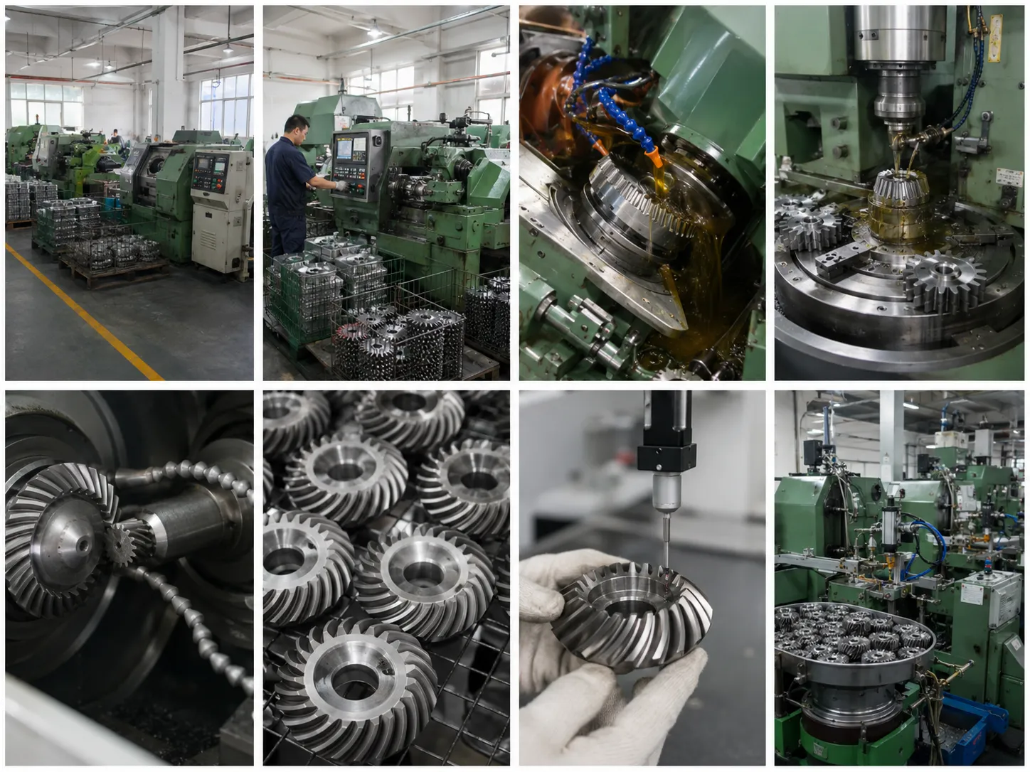
Korea Ever-Power large ring gear mining mill manufacturing workshop
Korea Ever-Power large-module ring gear manufacturing facility — segment machining on a large vertical CNC boring and turning machine. Large mining ring gear segments (OD 2–4 m per segment, weight 5–30 tonnes) require specialised handling and machining infrastructure: overhead gantry cranes of 50–100 tonne capacity, large-table CNC boring mills with 4–5 m table diameter and 10+ tonne table load capacity, and specialised gear hobbing attachments for the vertical machining centre that allow gear cutting of the tooth profile on the ring OD after the structural machining is complete. Korea Ever-Power’s manufacturing facility includes the complete machining sequence for mining ring gear segments in-house — forging or casting inspection, rough and semi-finish turning, tooth hobbing, flame or induction hardening, finish machining of bearing and joint faces, and all NDT (UT, MPI) before the segment is cleared for shipment. This end-to-end in-house capability is critical for controlling the quality of the critical machining datums that determine the gear quality of the assembled segmented ring — outsourcing of any machining step introduces re-fixturing datum errors that cannot be corrected without complete disassembly and re-machining.
Korea Ever-Power large ring gear mining ball mill types manufacturing
Korea Ever-Power large ring gear range — from 800 mm OD internal ring gears for planetary drives (upper left) to 4,000 mm OD segmented ring gears for ball mill drives (background). The transition from one-piece to segmented ring gear construction occurs at approximately 3,000 mm OD — below this diameter, the ring can be manufactured and transported as a single piece, while above it the segment joint bolting flanges and on-site assembly are required. All Korea Ever-Power mining ring gears are supplied with a dimensional inspection report that covers the key measurements the site installation team will use to verify the replacement: OD at 8 angular positions (confirms circularity), face width at 6 axial positions (confirms flatness), tooth thickness at 4 positions around the circumference (confirms uniformity of the hobbing or shaping), and bolt hole position at all bolt holes (confirms the bolt pattern matches the mill shell flange). This inspection report accompanies each segment and allows the site installation team to plan the assembly sequence — installing the lowest-OD segment at the bottom and the highest-OD at the top to compensate for the bolt flange step that would otherwise arise from OD tolerance variation between segments.

Frequently Asked Questions — Ring Gears for Mining Machinery

Q 01

Our 6-metre OD ball mill ring gear shows edge loading on the drive side tooth flank — the paint marking from our laser alignment check shows contact concentrated on the pinion-side edge of the tooth face. What is causing this and how do we correct it?

Edge loading concentrated at the pinion-side end of the ball mill ring gear tooth face is a classic misalignment symptom — the pinion shaft and the ring gear shaft are not parallel, causing the tooth contact to shift to one end of the face width instead of being centred across it. The root cause and correction sequence: (1) Confirm the direction of misalignment: paint the ring gear teeth on all 4 quadrants of the ring (top, bottom, drive side, opposite side) and run the mill empty for 5–10 revolutions. The contact pattern should show uniform distribution across the face width at all four positions if the ring gear is correctly aligned with the pinion. If the edge loading appears only at one quadrant or is rotated around the ring as the ring revolves, the misalignment is localised (a segment joint problem or a high spot in the ring mounting flange) rather than a systematic shaft angle error. (2) If systematic shaft angle error: the pinion shaft bearing supports must be adjusted. Most ball mill pinion housings have adjustable bearing housings that allow the pinion shaft to be tilted in both the horizontal and vertical planes by shimming the bearing housing feet. The required shim adjustment is calculated from the ratio of the edge loading offset to the ring gear face width — if contact is at the outer 20% of the face width, the pinion shaft requires approximately arctan(0.2 × face width / ring gear OD) correction in the appropriate plane. Contact Korea Ever-Power for the specific shim calculation for your mill. (3) If localised at one or two segment joints: the segment joint flanges at the high-contact position may have a step due to unequal segment face machining tolerance. Check the joint flatness with a straightedge across the joint and feeler gauges — a step of more than 0.2 mm requires shimming or re-machining of the lower segment flange face. Korea Ever-Power can provide an on-site measurement and alignment service for ball mill ring gear realignment if the above steps do not resolve the edge loading condition.

Q 02

What is the minimum planned shutdown time required to replace a 4-segment ball mill ring gear, and what installation sequence does Korea Ever-Power recommend?

Replacing a 4-segment ball mill ring gear (each segment is 90° arc) is a major planned maintenance activity that requires careful sequencing to minimise the shutdown duration while maintaining safety and alignment quality. Realistic minimum shutdown time with a well-prepared crew of 8–10 skilled millwrights and the appropriate lifting and alignment equipment: 72–96 hours (3–4 days) for a medium mill (OD 5–7 m, 30–60 tonne total ring gear mass). The recommended installation sequence: Day 1 (0–24 h): drain mill, remove pinion and pinion housing, remove mill discharge end trunnion liner, remove worn ring gear segment bolts (or cut if seized), remove the 4 worn segments using overhead crane. The worn ring gear removal is often the longest step if the joint bolts are corroded — budget 8–12 hours for removal. Day 2 (24–48 h): inspect the mill shell flange faces (the machined surfaces where the ring gear bolts) for corrosion, pitting, and flatness — repair any surface damage. Clean all bolt holes and re-tap if necessary. Install the first two opposite segments (positions 1 and 3) with new grade 10.9 bolts hand-tight only. Check the segment face alignment at the joint flanges with a straightedge and feeler gauges — correct any steps by shimming. Day 3 (48–72 h): install segments 2 and 4, verify joint alignment. Bring all bolt torques to 50% of the final torque value in a cross-pattern sequence (starting from the joint flanges outward). Reinstall pinion housing and set the pinion-to-ring gear mesh gap (backlash and axial position) per the mill manufacturer’s specification. Day 4 (72–96 h): final bolt torque to full specification in cross-pattern sequence. Paint tooth flanks and rotate mill by hand for first contact check. Commission mill at 25% load for 4 hours, re-check bolts. Korea Ever-Power provides an installation procedure document and bolt torque sequence drawing with all replacement ring gear segments.

Q 03

Should we specify induction hardened or QT (unhardened) teeth for a 4 MW copper mine ball mill replacement ring gear?

The choice between induction hardened and QT (quench and tempered, unhardened) teeth for a 4 MW copper mine ball mill replacement ring gear is one of the most debated specifications in mining gear engineering — both choices are defensible and used by major mining operations, and the correct choice depends on your specific mill operating conditions. Arguments for induction hardened teeth (HRC 48–54 tooth surface): higher contact fatigue resistance — the hardened surface can sustain Hertzian contact stresses 60–80% above the QT material’s endurance limit, meaning the ring gear can handle the same mill power at a smaller module (or handle higher power at the same module). Better wear resistance — the hard tooth surface resists the abrasive wear from mill feed dust that enters the open gear enclosure. Longer service life between replacements — hardened ring gears in similar applications typically achieve 15–20 years service life vs 8–12 years for equivalent QT rings. Arguments for QT (unhardened) teeth (HB 265–310): much lower risk of hardening distortion — induction hardening of a large segmented ring gear can produce 0.5–3 mm distortion of the ring segment flatness and tooth spacing, which must be corrected by post-hardening straightening and re-machining. The QT ring avoids this distortion risk entirely. Higher tooth root toughness for impact loads — the uniform QT hardness throughout the tooth cross-section provides better resistance to the sudden impact of large ore fragments entering the mill and transmitting through the charge to the shell. Lower manufacturing cost and shorter lead time. Korea Ever-Power recommendation for a 4 MW copper mine ball mill: if the mill processes competent hard rock (granite, porphyry) with occasional coarse ore above 150 mm at the mill feed, specify QT for the higher impact toughness. If the mill processes softer ore (oxide or transitional copper ore) at consistent feed size below 100 mm, specify induction hardened for the longer wear life. If uncertain, Korea Ever-Power can review the ore feed characterisation data (Bond Work Index, top size) and the mill operating record (previous ring gear wear history) before making a definitive recommendation.

Explore Korea Ever-Power Gear Categories

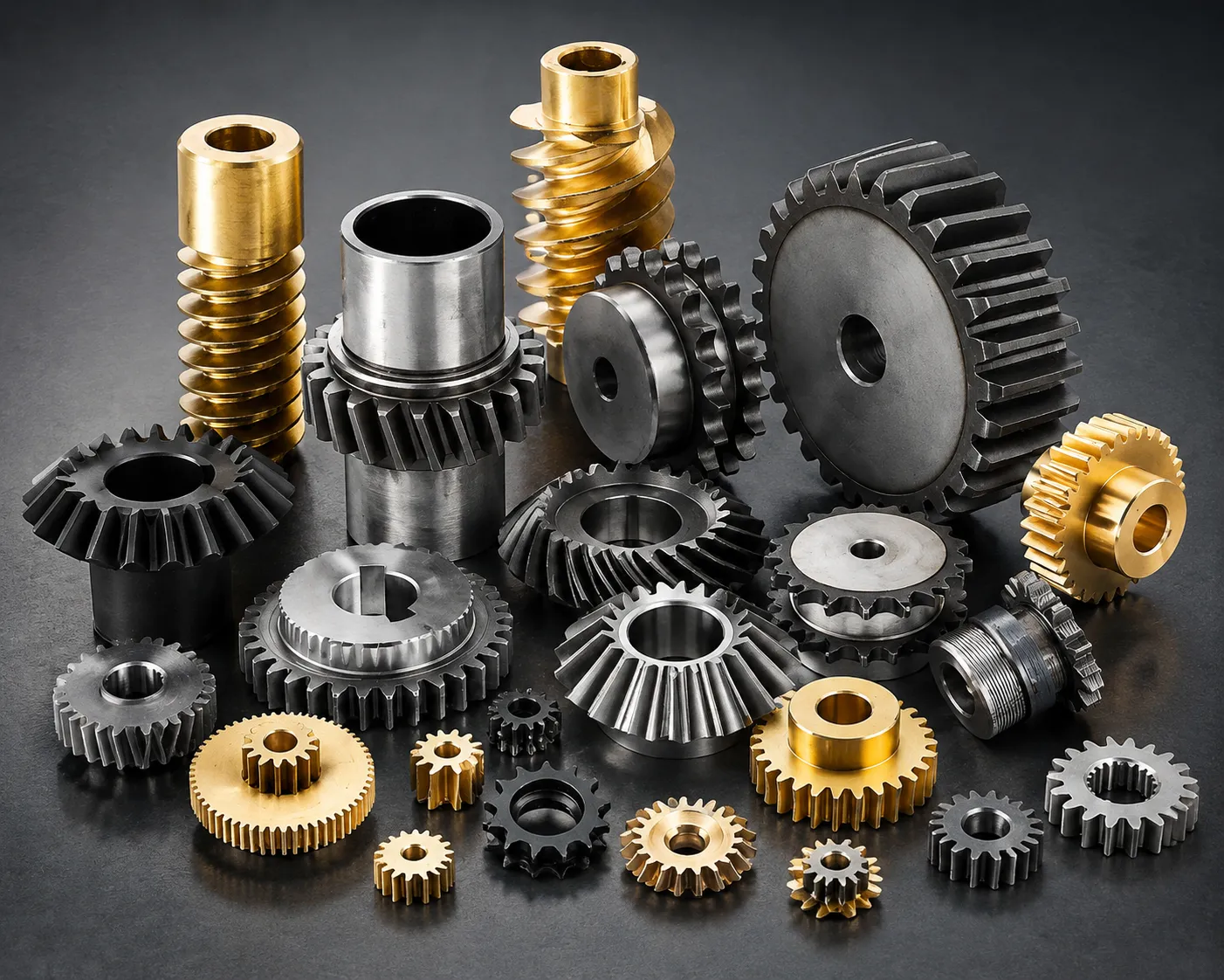
Seven precision gear product lines for mining machinery, ball mills, rotary kilns, dredges and heavy industrial rotating equipment worldwide.
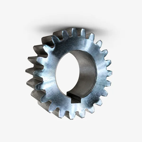
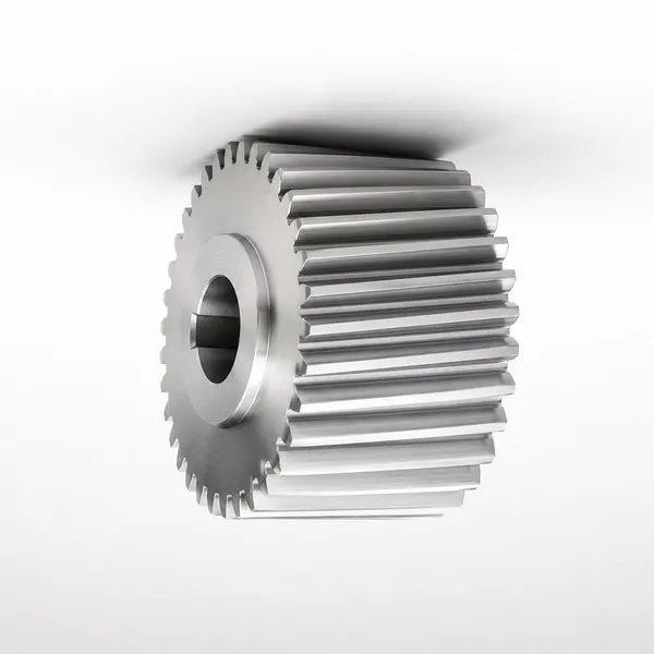
spur gear mining

Spur Gears

Mining auxiliary · conveyor · M5–M20

mining helical gear

Helical Gears

Mining gearbox · mill pinion · heavy

bevel gear mining

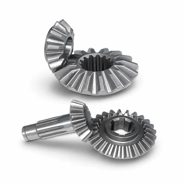
베벨 기어

Mine hoist · right-angle drive heavy

worm gear mining

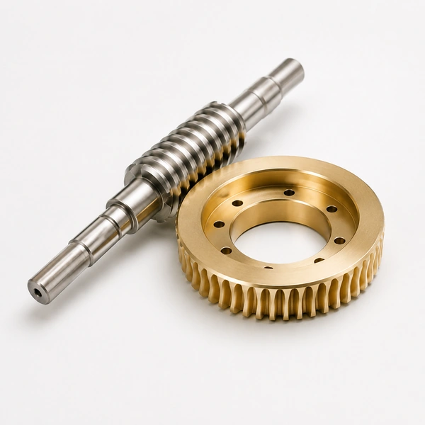
Worm Gears

Self-locking · mine hoist brake

ball mill ring gear mining

Ring Gears

Ball mill · SAG · kiln · M20–M50

planetary gear mining

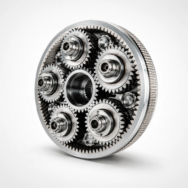
Planetary Gears

Mill pinion reducer · mine hoist

plastic gear

Plastic Gears

Sensor · instrument · mine control

GET A QUOTATION · KOREA EVER-POWER

Need Ring Gears for Mining Machinery?

Korea Ever-Power manufactures large-module ring gears for all mining machinery — SAG and ball mill ring gears (M20–M50, OD 1.5–12 m, 2–8 segments, forged or cast steel), cement and lime kiln rings (high-temperature specification), and dredge bucket wheel rings (high-toughness 34CrNiMo6). 100% UT and MPI NDT, segment joint alignment documentation, installation procedure and bolt torque schedule included. On-site alignment service available. ISO 9001:2015 certified.

Request a Quotation →

편집자: Cxm

VR Tour of Our Factory

TAGs:

기어랙

당사는 기어랙 제조, 공급 및 수출 분야의 선두 기업으로서 기어랙을 비롯한 다양한 제품을 제공합니다.

자세한 사항은 저희에게 문의해 주세요.

우편:[email protected]

기어랙 제조업체, 공급업체, 수출업체

최신 글

ko_KRKorean