
Ring Gears for Mining Machinery:
Ball Mill Drives, Rotary Kiln Rings and Large Diameter Mining Equipment
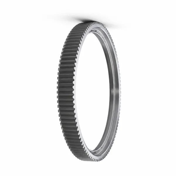
Mining machinery ring gears are the largest and heaviest gear components in any industrial application — the bull ring gear of a 36-foot diameter ball mill at an iron ore concentrator has an OD of 11 metres, weighs 80 tonnes, and is fabricated in segments that bolt together around the mill shell to form the complete ring. The forces transmitted through these gears are correspondingly massive: a 10 MW ball mill ring gear sustains tangential tooth loads of 800–1,200 kN at the pitch circle, while simultaneously being distorted and vibrated by the tumbling ore charge inside the mill that creates a fluctuating eccentric load on the shell and, through the shell, on the ring gear itself. Understanding and specifying ring gears for ball mills, rod mills, SAG mills, cement kilns, and large-diameter rotary dryers requires an engineering approach that combines standard gear fatigue analysis with the structural mechanics of large thin-ring deformation under eccentric load.
OD 1.5–12 m · DIN 8–10 · Segmented · 3–8 Segments
Ball Mill · SAG Mill · Rotary Kiln · Dryer · Cement
Ball Mill Ring Gear Engineering — Large Module, Segmented Design and Eccentric Load
The ball mill ring gear presents engineering challenges that do not exist in any other ring gear application. The combination of very large module (M20–M50), segmented construction (which introduces load discontinuities at the segment joints), and eccentric loading from the tumbling charge inside the mill creates a gear loading situation that standard ISO 6336 calculations cannot fully capture without additional corrections for the ring flexibility and the dynamic load from mill charge movement. The eccentric load arises because the ball charge in a grinding mill does not rotate symmetrically about the mill axis — as the mill rotates, the charge cascades in a characteristic waterfall pattern that places the centre of gravity of the charge approximately 10–20° offset from the lowest point of the mill. This offset between the charge centre of gravity and the mill axis creates a dynamic overturning moment on the mill shell that is transmitted to the ring gear as a fluctuating pitch alignment error at the ring gear-pinion mesh — the tooth contact band shifts from side to side across the face width with each mill revolution, generating a variable face load distribution factor KHβ that is significantly higher than the static value calculated from the tooth stiffness alone.
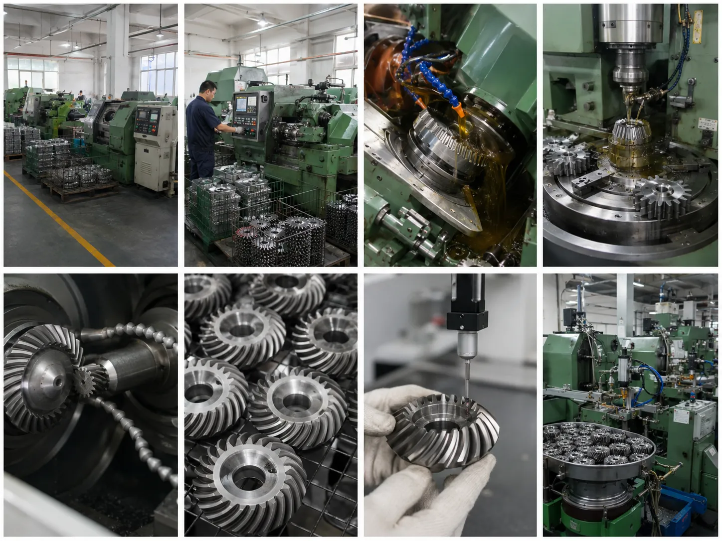
Korea Ever-Power’s ring gears for mining machinery are manufactured in both forged 42CrMo4 (for rings up to approximately 8 m OD where the forging mass per segment is within practical forge capacity) and cast steel G34CrNiMo6 (for the largest rings above 8 m OD, or for rings with complex cross-section profiles that integrate the bolt flanges and stiffening ribs as cast features rather than as machined features from a forged blank). The tooth profile for mining mill ring gears is generated by gear hobbing or gear shaping with large-module tools — the hob for M30 gear teeth has a tooth height of 67 mm and requires a dedicated CNC gear hobbing machine with sufficient radial depth of cut capacity, which limits the manufacturers worldwide who can produce these gears. Korea Ever-Power has the large-module tooling and CNC gear cutting capacity to produce ring gear segments up to M50 module, OD 4 m per segment (equivalent to a 12 m OD complete ring in 3 segments).
The segment joint design is one of the most critical engineering aspects of a segmented ball mill ring gear — the joint must transmit the full tooth load across the discontinuity between segments without any relative movement between segment ends (which would cause fretting damage at the joint flanges and progressive loosening of the joint bolts). The standard approach is a precision-machined, flanged butt joint with high-strength bolts (grade 10.9 minimum), where the bolts are torqued to a preload that generates a clamping force significantly higher than the maximum tangential tooth force at the joint position. Korea Ever-Power designs the joint bolt preload based on the joint friction coefficient and the maximum tooth tangential force at the joint position, with a minimum safety factor of 1.5 on the no-slip condition — the joint must not slip under any normal operating load. All joint flanges are machined on the same vertical CNC boring machine as the ring gear tooth reference surfaces, ensuring the flange faces are parallel to the gear axis and perpendicular to the tooth pitch tangent at the joint position, which is critical for the correct alignment of the assembled ring gear.
Mining Equipment Ring Gear Application Specifications
SAG and Ball Mill Ring Gears (3–12 m OD)
SAG (Semi-Autogenous Grinding) and ball mills are the primary size reduction equipment in hard rock mining — copper, gold, iron ore, and nickel processing plants use these mills to grind ore from run-of-mine size (150–200 mm) to the particle size required for flotation or magnetic separation (typically 75–150 μm). The ring gear is the power transmission interface between the pinion drive motor and the rotating mill shell — the ring gear runs at 10–20 RPM (the optimal mill rotation speed for grinding efficiency) driven by a pinion at the motor gearbox output at 50–100 RPM through a step-down ratio of approximately 3:1–6:1. Korea Ever-Power ball mill ring gears are designed with a minimum tooth bending fatigue life of 10⁷ cycles at rated tangential load — equivalent to approximately 10 years of continuous operation at typical mill rotation speeds. The very large module (M24–M36 for medium mills) means that each individual tooth contacts the pinion relatively infrequently per unit time, so the cumulative tooth cycle count over the design life is lower than for a high-speed gearbox despite the high transmitted power.
M24–M36 · OD 3–8 m · cast or forged segments · 10⁷ cycle life
Rotary Kiln Ring Gears (Cement / Lime)
Cement rotary kilns, lime kilns, and mineral calcination kilns use ring gears on the rotating kiln shell to transmit the slow rotation (0.5–4 RPM) from the pinion drive to the 60–200 m long kiln shell. The kiln ring gear (also called a kiln gear or kiln bull gear) operates at very low speed and with a dominant thermal load — the kiln shell operates at 300–400°C in the process zone, and the ring gear, which is bolted directly to the shell, reaches 150–250°C in service. This elevated operating temperature is the dominant design constraint for kiln ring gears: the material must retain adequate strength at 200°C (42CrMo4 loses approximately 10–15% of its yield strength at 200°C compared to ambient), the grease lubrication system must use a high-temperature open-gear lubricant (bitumen-based open gear compound for service to 250°C), and the thermal expansion of the ring relative to the kiln shell must be accommodated without residual stress buildup at the bolt flanges. Korea Ever-Power kiln ring gears are specified with a higher tooth bending safety factor (S_F ≥ 2.0, vs the standard S_F ≥ 1.5 for ball mills) to compensate for the material strength reduction at operating temperature.
M24–M40 · kiln temp 150–250°C · high-temp grease · S_F ≥ 2.0
Dredge Bucket Wheel Ring Gears
Bucket wheel excavators (BWE) and chain bucket dredges use ring gears on the bucket wheel drive to transmit the high torque needed to rotate the bucket wheel against the resistance of the excavated material (coal, lignite, sand, gravel). BWE bucket wheel ring gears differ from ball mill rings in their impact loading — the bucket wheel ring gear is subject to shock loads every time a bucket digs into the face, and the worst-case shock (a bucket hitting a hard inclusion in the coal seam or a buried boulder in a sand dredge) can be 5–8× the rated tangential load. This impact factor drives the BWE ring gear material specification toward higher-toughness steels — 34CrNiMo6 (higher nickel content for impact toughness) rather than 42CrMo4, and lower tooth hardness (HB 240–280 QT without additional surface hardening) to maximise the core impact toughness at the expense of wear resistance. The tooth module for BWE ring gears is typically M24–M36 with a large root fillet radius (0.4 × module) for maximum tooth root impact resistance.
34CrNiMo6 · high toughness · large fillet · shock KA = 3–5
Frequently Asked Questions — Ring Gears for Mining Machinery
Explore Korea Ever-Power Gear Categories
Seven precision gear product lines for mining machinery, ball mills, rotary kilns, dredges and heavy industrial rotating equipment worldwide.
編集者: Cxm
 Japanese
  English
  Italian
  Korean
  French