Spur Gears for Pump Drives: Centrifugal Pumps, Gear Pumps and Hydraulic Pump Auxiliaries
Pump drive spur gears serve a deceptively simple purpose — transmitting motor torque to the pump shaft at the correct speed ratio — yet they operate under conditions that challenge many standard gear designs: centrifugal pump drives must cope with the full motor starting torque (which can be 5–7× the rated running torque for a direct-on-line started motor), gear pump internals must meet the dimensional tolerances of the pump body to maintain the correct tip clearance that controls the pump’s internal leakage, and hydraulic pump auxiliary drives on mobile equipment must sustain the shock loads and vibration from the vehicle powertrain while maintaining hydraulic pressure for the implement circuit. This guide covers spur gear specification for all three pump drive contexts across water infrastructure, oil and gas, chemical process, and mobile hydraulics.
Pump drive spur gear module range. Gear pump internal rotors: M3–M6 (tight tolerance, tip clearance critical). Centrifugal pump parallel-shaft drive: M5–M10. Large centrifugal booster pump drive (desalination, water supply): M10–M16. Mobile hydraulic PTO gear drive: M4–M8. Each application has different tolerance and material priority
STARTING FACTOR
KS 1.5 – 2.5
Starting torque application factor for centrifugal pump drive spur gears. Direct-on-line (DOL) motor start: KS = 2.0–2.5 (peak motor starting torque 5–7× rated; gear sees 2–2.5× rated for duration of acceleration). Star-delta or VFD start: KS = 1.5–1.8. The spur gear must sustain the starting torque without tooth fracture for 10,000+ starts over the pump’s design life
GEAR PUMP CLEARANCE
±0.05 mm
Tip clearance tolerance between the gear pump rotor OD and the pump body bore. Internal gear pump and external gear pump both require this clearance to be maintained within ±0.05 mm of the design value — too large and the pump loses volumetric efficiency (internal leakage increases), too small and the rotor contacts the body under thermal expansion at operating temperature
ATEX OPTION
Zone 1 / 2
Pump drive spur gears for ATEX Zone 1 (explosive gas atmosphere present continuously or frequently) and Zone 2 (explosive atmosphere present occasionally) applications — chemical process pumps, LNG, refinery. ATEX requirements: non-sparking materials (bronze or aluminium for exposed gears), maximum surface temperature below auto-ignition temp, and enclosed gear drive without potential ignition sources
Pump Drive Spur Gear Engineering — Three Applications, Three Design Priorities
The spur gear appears in three functionally distinct pump drive contexts, each demanding a different engineering priority. In the centrifugal pump parallel-shaft drive (where the motor and pump have non-coaxial shafts and a spur gear pair bridges the speed ratio and axis offset), the priority is fatigue life under the cyclically variable torque of centrifugal pump operation — the pump torque varies as the square of the flow rate, which itself varies as the pump operates across different points on its head-flow characteristic curve as system demand changes. In the internal gear pump (where the spur gear IS the pump element — a cycloidal or involute internal rotor pair that traps fluid between the teeth and the pump body), the priority is dimensional accuracy of the rotor to body clearance, which directly controls the volumetric efficiency. In the mobile hydraulic PTO pump drive (where a spur gear on the power take-off shaft drives a hydraulic gear pump for excavator implements, tractor loaders, or truck-mounted cranes), the priority is shock and impact resistance from the engine torque pulses and implement load reversals.
Korea Ever-Power’s spur gears for pump drives are manufactured across all three contexts — 42CrMo4 QT and 20CrMnTi carburized for centrifugal pump parallel-shaft drives and mobile hydraulic PTO pump drives, grey cast iron (GGG50) and 316L stainless for internal gear pump rotors in water, chemical, and food service, and non-sparking bronze CuSn8 for ATEX Zone 1 and Zone 2 pump drive applications. The production range covers M3 through M16 with quality class DIN 6 through DIN 8 depending on the application precision requirement — centrifugal pump drives at DIN 7–8 (where cost is the primary criterion and transmission error is not the design driver), gear pump rotors at DIN 6 (where the rotor OD accuracy directly affects volumetric efficiency), and speed-increasing pump drives (where the pump runs faster than the motor — common in booster pump sets) at DIN 6–7 for the higher pitch line velocity.
The DOL (direct-on-line) motor start condition imposes a design challenge that is often underestimated in pump drive gear specifications. A 4-pole induction motor driving a centrifugal pump DOL draws 5–7× its full-load current during starting and produces a peak torque of 2–3× its rated torque at approximately 80% of synchronous speed during the acceleration transient. This starting torque peak is applied to the pump drive spur gears during every start event — which, in a water supply pump station with frequent demand cycles, may occur 20–50 times per day. Over a 20-year pump life, the spur gear accumulates 150,000–365,000 starting torque cycles at 2–3× rated torque — a significant fatigue loading that must be included in the service factor calculation alongside the normal running load fatigue. Korea Ever-Power uses a starting factor KS in the gear design service factor (SF = KA × KS × KHβ × KHα × Kv) based on the motor starting method — KS = 2.5 for DOL, 1.8 for star-delta, and 1.5 for variable frequency drive (VFD) soft-start — to ensure the gear tooth bending fatigue safety factor S_F ≥ 1.5 at the peak starting torque condition as well as at the rated running condition.
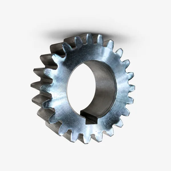
Korea Ever-Power 42CrMo4 QT through-hardened spur gear for centrifugal pump parallel-shaft drive — M8, 38 teeth, OD 320 mm, face width 80 mm, HB 300–340, DIN 7 quality class. Designed for direct-on-line motor start service (KS = 2.5), 500 kW motor rating, 1,470 RPM motor speed, 960 RPM pump speed (gear ratio 1.53:1). Bending fatigue safety factor S_F = 1.62 at starting torque (peak 2.5× rated), S_F = 3.1 at rated running torque — the higher rated running margin confirms the gear is starting-torque-limited, not running-torque-limited, which is typical for DOL pump drives. The gear is supplied as a matched pair (pinion + wheel) with the pinion in 20CrMnTi case carburized (for higher fatigue resistance per the smaller pinion’s higher stress concentration) and the wheel in 42CrMo4 QT — the differential hardness pair (HRC 58–62 pinion, HB 300–340 wheel) promotes initial run-in contact pattern development and extends the paired gear set’s life beyond an equivalent same-material pair.
Pump Drive Application Specifications
PUMP 01
CENTRIFUGAL PUMP
PARALLEL DRIVE
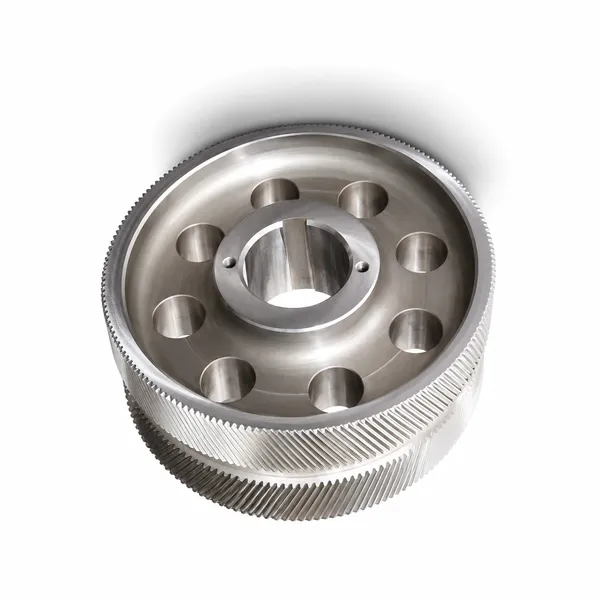
Spur gear specification: M5–M14, differential hardness pair (20CrMnTi carburized pinion + 42CrMo4 QT wheel), DIN 7–8, starting factor KS per motor start method, centre distance held within ±0.05 mm for proper backlash. Centrifugal pumps — water supply and distribution, irrigation, cooling water, fire fighting, and process pumps — are the single largest pump category and produce the highest volume demand for pump drive spur gears. The parallel-shaft arrangement (motor shaft and pump shaft parallel, connected by a spur gear pair) is used when the motor speed does not match the pump speed, or when the motor and pump cannot be directly coupled due to the pump’s overhung impeller mass requiring the motor to be offset from the pump shaft centreline. Desalination plant booster pump drives in the 500 kW–5 MW power range use M10–M16 spur gear pairs in 42CrMo4 or 20CrMnTi, with the gear set often the largest-cost single component in the pump station mechanical equipment. Korea Ever-Power desalination pump drive spur gears are specified with an enhanced corrosion inhibitor coating on all non-tooth machined surfaces (the bore, keyway, and side faces) to prevent surface rust from the humid coastal environment during transport and storage at the desalination plant site before commissioning.
PUMP 02
EXTERNAL GEAR
PUMP ROTORS
Spur gear specification: M3–M6, hobbed and lapped (not profile ground — the lapping produces the smooth, matched rotor-to-rotor and rotor-to-body fit that controls volumetric efficiency), tip OD tolerance within ±0.02 mm of the pump body bore (to maintain the 0.05–0.15 mm tip clearance that is the primary volumetric efficiency parameter), face width matched pairs from the same production cut. External gear pumps (used for hydraulic oil transfer in mobile equipment, lube oil pumping in engines and compressors, chemical transfer in process plants, and fuel transfer) use a matched pair of spur gears as the pumping elements — fluid is trapped between the gear teeth and the pump body as the gears rotate outward from the mesh zone and transported around the periphery to the outlet port. The OD tolerance of the gear rotor is the most critical dimension — Korea Ever-Power gear pump rotors are ground to OD tolerance h5 (within 0.011 mm for M4 gears) and individually measured before pairing, with the matched pair’s tip clearance calculated and documented. Gear pump rotors are supplied in matched sets and are not interchangeable with rotors from different manufacturing batches, even of the same part number — the matched pairing is essential for the correct meshing noise and volumetric efficiency.
PUMP 03
MOBILE HYDRAULIC
PTO PUMP DRIVE
Spur gear specification: M4–M8, 20CrMnTi carburized, DIN 7, shock factor KA = 1.5–2.0 (for agricultural tractor PTO: KA = 1.5; for truck-mounted hydraulic crane pump: KA = 2.0), sealed housing for dust and water ingress protection (IP54 minimum). Mobile hydraulic pump drives (the gear train between the vehicle engine or transmission PTO and the hydraulic gear pump that powers the implement circuit) are exposed to the most severe shock loading of any pump drive spur gear application. An agricultural tractor PTO pump drive experiences the rotary torque pulses of the diesel engine at combustion frequency — at 2,000 RPM with 4 cylinders, this is 67 Hz torque pulsation imposed on the PTO spur gears. An excavator hydraulic pump drive experiences the combined shock of engine torque pulses, track travel impacts, and the sudden pressure surges when the operator opens the implement control valve against the hydraulic system relief valve. Korea Ever-Power mobile hydraulic PTO pump drive spur gears are specified with root fillet radius at 0.3 × module (larger than the standard 0.2 × module) to reduce the stress concentration at the gear tooth root under these shock loads, improving impact fracture resistance at the expense of a slight reduction in the contact ratio and addendum tooth area.
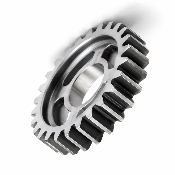
Korea Ever-Power 20CrMnTi forged blank spur gear for mobile hydraulic PTO pump drive application — M6, 24 teeth, OD 156 mm, face width 60 mm, case carburized HRC 58–62, DIN 7 quality class, enlarged root fillet radius 1.8 mm (0.3 × module vs standard 1.2 mm). Forged blank (not bar-machined): the forging process aligns the steel grain flow around the tooth profile, creating a fibre flow pattern that increases the tooth root impact fracture resistance by 20–30% vs a machined-from-bar gear of the same specification. The forging traceability (heat number, forge date, forging die number) is retained in Korea Ever-Power’s production records for 5 years, enabling the failure analysis of any field-returned gear to be correlated with the specific melt and heat treatment batch. Korea Ever-Power forged pump drive spur gears are used as OEM replacements in Bosch Rexroth, Parker Hannifin, and Eaton Vickers hydraulic pump drive assemblies on agricultural tractors, excavators, and truck-mounted hydraulic equipment.
ATEX Pump Drives and Special Environment Spur Gears
Chemical process plants, LNG terminals, petroleum refineries, and paint manufacturing facilities require pump drives that comply with ATEX Directive 2014/34/EU (or IECEx for non-EU markets) — the European regulation governing equipment intended for use in explosive atmospheres. The ATEX requirements that affect pump drive spur gears specifically are: (1) maximum surface temperature classification (T-class, ranging from T1 = 450°C maximum to T6 = 85°C maximum, determined by the auto-ignition temperature of the explosive gas or vapour present); (2) avoidance of electrostatic charge accumulation on non-conductive parts; (3) avoidance of sparking from gear tooth impact that could ignite the explosive atmosphere. Standard steel spur gears, when two teeth impact in the event of a tooth fracture or debris between the teeth, can produce metallic sparks at temperatures of 1,000–2,000°C — well above the ignition temperature of most flammable gases.
ATEX PUMP DRIVE SPUR GEAR — MATERIAL SELECTION BY ZONE
ZONE 1 (GAS ALWAYS PRESENT)
• Material: phosphor bronze CuSn8 or aluminium bronze CuAl10Ni5Fe4 — both are non-sparking materials that cannot generate incendiary sparks even in catastrophic tooth fracture
• Load limit: bronze spur gears have 40–50% of the load capacity of equivalent steel gears at the same module — increase module by one step when substituting from steel to bronze at the same application load
• Housing: aluminium alloy (non-sparking) with earthing terminal to prevent electrostatic charge; external fasteners in stainless or brass
ZONE 2 (GAS PRESENT OCCASIONALLY)
• Material: stainless steel 316L or austenitic stainless (non-magnetic, low sparking tendency compared to carbon steel, corrosion resistant for chemical environments)
• Alternatively: nitrided 316L stainless for improved tooth hardness (HV 900 after plasma nitriding) while maintaining non-sparking property — Korea Ever-Power can supply 316L plasma nitrided spur gears for Zone 2 at M3–M8
• Enclosed housing with IP65 sealing to prevent gas ingress, earthing terminal, temperature class T3 (200°C maximum surface) as standard for petrochemical Zone 2
NON-ATEX CORROSIVE ENVIRONMENTS
• Seawater pump drives: duplex stainless 2205 (UNS S31803) for superior crevice corrosion resistance over 316L in seawater service — Korea Ever-Power supplies 2205 spur gears at M4–M10 for marine pump drives
• Acid service (pH < 4): Hastelloy C276 for fuming acid pump drives, or PVDF/PEEK plastic gears at M3–M5 for very low-load acid dosing pump drives where full immersion in the acid is unavoidable
• Chlorine/bleach service: 316L minimum, Hastelloy C276 for concentrated hypochlorite; avoid all copper alloys — bleach attacks brass, phosphor bronze, and aluminium bronze rapidly
Korea Ever-Power precision measurement for pump drive spur gears — gear pump rotor OD measurement on a CMM with 0.001 mm resolution, confirming rotor tip OD within the ±0.02 mm tolerance required for correct tip clearance with the pump body. The tip clearance (the gap between the rotor OD and the pump body bore) is the single most important dimension in a gear pump — at rated operating pressure of 20–30 bar, the fluid leaks backward through the tip clearance gap at a rate proportional to (clearance)³ / (viscosity × gap length). A tip clearance of 0.08 mm instead of the design 0.05 mm (a 60% oversize) increases the internal leakage by (0.08/0.05)³ = 4× — reducing volumetric efficiency from the designed 92% to approximately 80%. Korea Ever-Power gear pump rotors are individually measured for OD at 8 equally-spaced angular positions and issued with a diameter range certificate: any rotor showing OD variation greater than 0.005 mm around the circumference (indicating eccentricity or out-of-round) is rejected regardless of being within the mean diameter tolerance.
Frequently Asked Questions — Spur Gears for Pump Drives
Q 01
Our 315 kW water supply centrifugal pump drive gear failed after 14 months — tooth fracture at the pinion root. The pump is DOL started 30–40 times per day. What should we specify for the replacement?
Pinion tooth root fracture at 14 months with 30–40 DOL starts per day is a classic fatigue failure from insufficient starting torque margin. At 35 starts per day for 14 months (420 days operating): approximately 15,000 starting torque cycles at 2–3× rated torque. If the original pinion was specified only for running fatigue (bending safety factor S_F ≥ 1.5 at rated torque) without adequate starting torque margin, the pinion tooth root may have been at S_F = 1.1–1.2 at the DOL starting torque — insufficient for 15,000 high-amplitude fatigue cycles. Replacement specification: (1) Upgrade material from C45 to 20CrMnTi carburized: if the original pinion was C45 induction hardened (HRC 48–54 at the tooth surface, with a relatively thin hardened case below the root fillet), upgrade to 20CrMnTi case carburized. The carburized pinion has a deeper hardened case (effective case depth 1.2–1.8 mm for M8 gear) that fully encompasses the root fillet stress concentration zone, providing the endurance limit bending stress (σ_FE) at the root fillet — C45 induction hardening does not always achieve full case depth at the root fillet. (2) Apply starting factor KS = 2.5 in the service factor calculation: recalculate the pinion size using SF_total = KA × KS × Kv × KHβ × KHα with KA = 1.25 (moderate vibration from centrifugal pump) and KS = 2.5 (DOL start). If this recalculation shows S_F < 1.5 at the starting torque for the current pinion size, increase the module by one step. (3) Consider VFD control: fitting a variable frequency drive (VFD) to the pump motor reduces the starting torque from 2.5× to 1.5× rated, extending the gear start fatigue life by approximately (2.5/1.5)³ = 4.6× — the most cost-effective intervention for high-frequency start applications. The VFD payback (from both gear life extension and energy savings in the pump station) typically is achieved in 12–18 months for a 315 kW pump motor.
Q 02
Our gear pump is showing reduced output pressure and flow after 6 months of operation. The rotors are within dimensional tolerance individually, but the pump is underperforming. What is happening?
Gear pump volumetric efficiency loss despite individually-compliant rotor dimensions indicates the tip clearance has increased beyond the design value due to one of two mechanisms: (1) Wear of the pump body bore: the rotor OD (which you have confirmed is within tolerance) is running against a pump body bore that has worn from the abrasive particles in the pumped fluid. Measure the pump body bore at 4–8 angular positions around the circumference — if the bore has increased by more than 0.1 mm from the drawing dimension, the body must be replaced. Even though the rotor OD is correct, the increased bore gives a tip clearance of rotor OD + bore wear, which can be 2–3× the design clearance value. (2) Rotor face wear: the axial faces of the rotors run against the pump end plates, and the clearance between the rotor face and the end plate is the second volumetric efficiency parameter (end clearance, typically 0.02–0.04 mm). If the fluid contains abrasive particles (sand, scale, pipe rust), the rotor faces and end plates wear simultaneously, increasing the end clearance and dramatically reducing volumetric efficiency — this wear mode is less obvious because the rotor face wear cannot be measured while the pump is assembled. Diagnosis: (a) Measure the pump body bore as above. (b) Disassemble and measure the rotor face runout (the difference in axial face position across the face diameter — should be below 0.005 mm for a precision gear pump). (c) Check the end plates for visible scoring or abrasive wear tracks. (d) Install a 25 μm suction strainer if not already fitted — this is the most effective preventive measure for abrasive wear in gear pumps handling fluid from open reservoirs or systems without filtration. Korea Ever-Power supplies matched replacement rotor sets and end plate sets for all major gear pump models, dimensioned to restore the original tip and end clearances.
Q 03
What is the lead time and minimum order for pump drive spur gears at M6–M10 in 42CrMo4 and 20CrMnTi for stock and emergency supply?
Korea Ever-Power pump drive spur gear supply parameters: Stock items (M6, M8, M10 standard tooth counts in 42CrMo4 QT and 20CrMnTi carburized with standard bore sizes 30, 40, 50, 60, 80, 100 mm): available for dispatch within 3–7 working days. Standard tooth counts stocked: 18T, 24T, 30T, 36T, 42T in the M6–M10 range. These cover the majority of centrifugal pump parallel-shaft drives in the 100–800 kW power range. Minimum order for stock items: 1 piece. Non-standard tooth counts, non-standard bores, or exact replacement for a specific pump brand: lead time 12–18 working days; minimum order 2 pieces. For emergency pump station situations (unplanned failure requiring immediate replacement), Korea Ever-Power offers a 48-hour emergency supply service for stock-matched items — priority machining of the bore and keyway to the customer’s exact dimension from the stock blank. Emergency service applies to M6–M12 in 42CrMo4 QT and carries a 30–40% premium over the standard price. ATEX-compliant bronze spur gears (M4–M10, CuSn8 phosphor bronze): lead time 15–25 working days; minimum order 2 pieces. ATEX documentation (material certificate confirming non-sparking alloy, surface temperature calculation) supplied with every ATEX gear order at no additional charge. Contact Korea Ever-Power with the tooth count, module, bore, face width, and application detail for a stock check and quotation response within 24 hours for standard sizes.
Explore Korea Ever-Power Gear Categories
Seven precision gear product lines for pump drives, water infrastructure, chemical process and mobile hydraulic applications worldwide.
Korea Ever-Power manufactures pump drive spur gears in 42CrMo4, 20CrMnTi, 316L stainless, phosphor bronze (ATEX Zone 1), and duplex stainless for all pump drive applications — centrifugal pump parallel-shaft drives (M5–M16, starting factor KS up to 2.5), gear pump rotors (M3–M6, OD tolerance h5, matched pairs), and mobile hydraulic PTO drives (M4–M8, shock KA 2.0, forged blanks). 48-hour emergency supply for stock sizes. ISO 9001:2015 certified.


 Japanese
  English
  Italian
  Korean
  French