
Ring Gears for Slewing Drives:
Crane Slewing Rings, Solar Tracker Drives and Excavator Slew Mechanisms
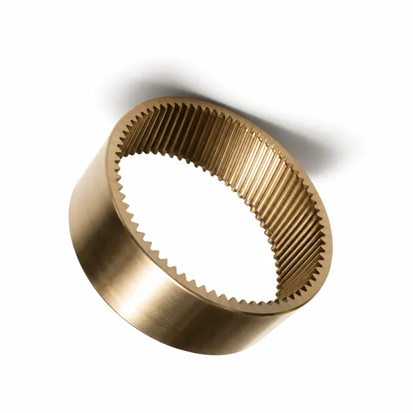
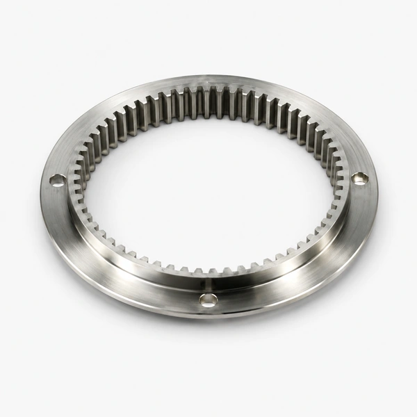
Slewing drive ring gears are among the most dimensionally imposing gear components in industrial machinery — the slewing ring gear of a 100-tonne mobile crane has an OD of 2.5–3.5 metres and must transmit the full superstructure slewing torque while simultaneously carrying the combined radial, axial, and moment loads from the crane boom through an integrated raceway bearing. The design integration of the ring gear tooth profile, the rolling element bearing raceway, and the structural cross-section of the slewing ring represents a unique engineering challenge that differs fundamentally from all other ring gear applications, and that demands a manufacturing process — hobbing or profile grinding the gear teeth on the same part as the precision-ground bearing raceway — that requires specialised machinery found in only a handful of gear manufacturers worldwide.
Internal / External · DIN 7–9 · Induction Hardened
Crane · Solar · Excavator · Wind · Medical
Slewing Drive Ring Gear Engineering — Combined Gear and Bearing Design
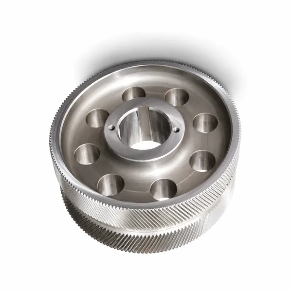
The slewing ring gear is the only standard gear component that simultaneously functions as a gear and a rolling element bearing — the same ring forging contains both the precision-machined gear tooth profile on its periphery (inner or outer depending on the configuration) and the hardened, ground rolling element raceway on its face. This design integration creates a manufacturing sequence that is unique among gear types: the blank must be rough-machined, QT heat treated, semi-finish machined (both tooth profile and raceway reference surfaces), induction hardened (both the tooth flanks and the raceway in the same or adjacent operations), and then finish-ground (the raceway) and finish-hobbed (the tooth profile) with the bearing reference surfaces used as the datum for both machining operations, ensuring concentricity between the gear pitch cylinder and the bearing raceway to within 0.1–0.3 mm TIR depending on the ring diameter.
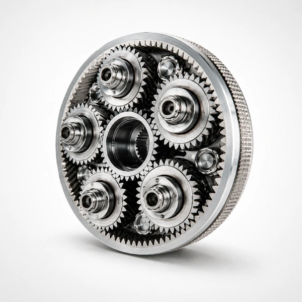
Korea Ever-Power’s ring gears for slewing drives are manufactured in 42CrMo4 (for crane and excavator applications under European standards), 42CrMo (for solar tracker, standard industrial, and Chinese-market excavator slewing rings under GB standards), and 50Mn (for large crane slewing rings where the higher manganese content provides better through-hardening depth in the thick cross-sections of large-diameter rings). The manufacturing process for Korea Ever-Power slewing ring gears follows the DIN 3992 and ISO 6336 calculation standards for gear capacity, combined with ISO 76 bearing load rating calculation for the integrated bearing function — the slewing ring is both a gear and a bearing, and both functions must be independently rated for the combined loads at each application. For applications requiring a complete slewing drive assembly including the pinion, motor, and housing, Korea Ever-Power’s planetary gearbox product line covers several configurations that integrate with standard slewing ring gears.
The combined load analysis of a slewing ring gear is fundamentally different from a standard ring gear load analysis because the slewing ring carries three types of simultaneous load: the tangential (torque) load from the drive pinion engaging the ring gear teeth, the axial load from the weight of the superstructure being slewed (which compresses the bearing raceway axially), and the overturning moment from the offset between the superstructure centre of gravity and the slewing ring centreline (which creates a tilting moment that increases the load on one side of the bearing raceway while reducing it on the other). The equivalent bearing load for a slewing ring bearing is calculated from these three simultaneous components using the ISO TR 10715 method, which combines them into a single equivalent radial load for the rolling element fatigue life calculation. Korea Ever-Power performs this combined load analysis for each custom slewing ring gear application and provides the calculated bearing L10 life (the number of slewing revolutions at which 90% of a batch of rings would be expected to survive without bearing fatigue failure) alongside the gear tooth bending and contact fatigue safety factors in the application engineering report.
Slewing Drive Application Specifications
Slewing Ring Gear Installation, Greasing and Maintenance
The service life of a slewing ring gear is determined primarily by the lubrication and maintenance quality during operation — the bearing raceway fatigue life (calculated as 50,000–200,000 slewing revolutions depending on load and ring size) assumes adequate lubricant film in the rolling element contact zone at all times. In practice, slewing rings on cranes and excavators operate in outdoor environments where the greasing interval is difficult to maintain precisely, the grease can be diluted or washed out by rain or high-pressure cleaning, and the bearing raceway and gear teeth are simultaneously exposed to abrasive contamination (sand, grit, concrete dust on construction sites). The combination of inadequate lubrication and abrasive contamination is the most common cause of premature slewing ring failure in field service.
SLEWING RING GEAR — MAINTENANCE PARAMETERS
GEAR TOOTH GREASING
- • Grease type: open-gear grease, NLGI 0 or 00 (semi-fluid) for continuous application from an automatic lubricator; NLGI 2 EP for manual greasing intervals
- • Interval: manual greasing every 100–250 hours of slewing operation, or every 50 hours in dusty/wet conditions. Automatic lube systems: every 8–20 hours depending on the system flow rate and the ring circumference
- • Application method: brush-apply grease to the tooth flanks with the ring rotating at low speed — ensures coverage on all tooth faces, not just the accessible arc
RACEWAY GREASING
- • Grease type: NLGI 2 lithium or lithium-complex EP grease suitable for the bearing raceway operating temperature (−20°C to +80°C in most crane and excavator applications)
- • Interval: every 50–100 hours of operation via the grease nipple pattern on the ring (typically 4–8 nipples equally spaced around the ring circumference)
- • Volume: grease until fresh grease appears at the labyrinth seal — confirms all raceway segments have been reached
- • After washing or high-pressure cleaning: always regrease immediately, since water displaces grease from the raceway contact zone
BOLT PRELOAD INSPECTION
- • Bolt preload loss is the second most common slewing ring failure precursor — the mounting bolts loosen from the dynamic loads of crane slewing, reducing the clamping force on the ring and allowing the ring to rock in its seat under moment load, producing fretting damage at the ring/structure interface
- • Inspection interval: check bolt torque values at every 500 hours or annually (whichever is sooner); re-torque to specification if any bolt has lost more than 10% of its installation torque value
- • Bolt grade: minimum grade 10.9 (ISO 898-1) for all slewing ring mounting bolts — grade 8.8 is undersized for the clamp load requirement and must not be substituted
Frequently Asked Questions — Ring Gears for Slewing Drives
Explore Korea Ever-Power Gear Categories
Seven precision gear product lines for slewing drives, cranes, excavators, solar trackers and large rotating machinery worldwide.
Redattore: Cxm
 Italian
  English
  Korean
  French
  Japanese